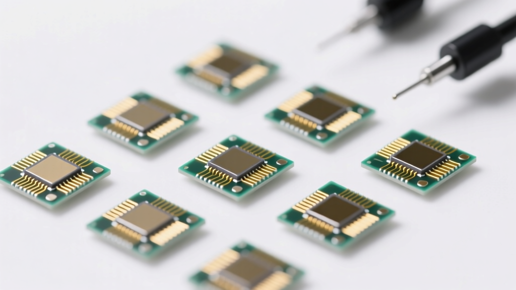
Types of Modbus RTU Energy Meter Modules
A Modbus RTU energy meter module is a digital device used in industrial and commercial power systems to monitor, measure, and transmit electrical parameters via the Modbus RTU communication protocol. These modules are essential for energy management, cost allocation, system diagnostics, and compliance with efficiency standards. They vary significantly in functionality, application, and measurement capabilities.
Single-Phase Energy Meter Modules
Designed for single-phase AC power systems, these modules are commonly used in residential buildings, small offices, and light commercial applications.
Advantages
- Cost-effective and easy to install
- Measures key parameters: voltage, current, power, energy, and power factor
- Supports basic energy monitoring and billing
- Ideal for low-voltage distribution systems
Limitations
- Limited to single-phase systems only
- Fewer advanced analytics compared to three-phase meters
- Not suitable for heavy industrial loads
Best for: Homes, small retail spaces, and individual circuit monitoring
Three-Phase Energy Meter Modules
Engineered for three-phase electrical systems, these modules provide comprehensive monitoring across all three phases—R, S, and T—commonly found in industrial plants, data centers, and large commercial facilities.
Advantages
- Accurate per-phase and total energy measurement
- Supports load balancing analysis
- Monitors harmonics, frequency, and reactive power
- Essential for large-scale energy audits and efficiency optimization
Limitations
- Higher cost than single-phase variants
- More complex installation and configuration
- Requires skilled personnel for calibration
Best for: Factories, commercial buildings, HVAC systems, and motor control centers
Multifunction Energy Meter Modules
These advanced modules integrate the measurement of multiple electrical parameters into a single device, offering detailed insights into power quality and system performance.
Advantages
- Measures voltage, current, active/reactive/apparent power, kWh, kVARh, power factor, frequency, and harmonics
- Reduces need for multiple standalone meters
- Supports predictive maintenance and fault detection
- High accuracy and scalability in complex systems
Limitations
- Premium pricing due to advanced features
- Requires proper configuration and integration
- May need additional software for full data utilization
Best for: Industrial automation, power distribution panels, and critical infrastructure monitoring
Submetering Energy Meter Modules
Specifically designed for granular energy tracking, submetering modules enable cost allocation by measuring consumption in individual zones, departments, or tenant units within a larger facility.
Advantages
- Enables accurate utility billing in multi-tenant buildings
- Identifies energy waste and inefficiencies
- Supports sustainability reporting and LEED certification
- Facilitates departmental energy accountability
Limitations
- Requires network infrastructure for data aggregation
- Higher upfront investment for large-scale deployments
- Needs ongoing data management and analysis
Best for: Apartment complexes, office buildings, campuses, and manufacturing floors
Smart Energy Meter Modules
Equipped with communication capabilities, smart meters go beyond basic measurement by enabling real-time monitoring, remote access, and integration with SCADA, BMS, or IoT platforms via Modbus RTU or other protocols.
Advantages
- Real-time data transmission and cloud connectivity
- Automated data logging and reporting
- Remote configuration and diagnostics
- Supports demand response, load forecasting, and anomaly detection
Limitations
- Dependent on network stability and cybersecurity measures
- Higher initial cost and complexity
- May require firmware updates and IT support
Best for: Smart grids, energy management systems (EMS), and Industry 4.0 applications
| Type | Phase Support | Key Parameters | Communication | Typical Use Case |
|---|---|---|---|---|
| Single-Phase | 1-Phase | Voltage, Current, Power, Energy, PF | Modbus RTU | Residential, small offices |
| Three-Phase | 3-Phase | All parameters + per-phase data, harmonics | Modbus RTU | Industrial plants, commercial buildings |
| Multifunction | 1P/3P | Comprehensive power quality metrics | Modbus RTU (often with extended registers) | Power monitoring, maintenance |
| Submetering | 1P/3P | Energy consumption, kWh tracking | Modbus RTU + network integration | Tenant billing, cost allocation |
| Smart Meter | 1P/3P | Full parameter set + analytics | Modbus RTU + IoT/SCADA integration | Smart buildings, predictive analytics |
Expert Tip: When deploying Modbus RTU energy meters, ensure proper termination resistors (120Ω) are used on the RS-485 bus and maintain cable shielding to prevent communication errors in electrically noisy industrial environments.
Features of Modbus RTU Energy Meter Module
Modbus RTU energy meter modules are advanced monitoring devices designed to deliver precise, real-time electrical data across industrial, commercial, and residential environments. Their combination of measurement accuracy, communication reliability, and rugged design makes them ideal for energy management, system diagnostics, and cost optimization. Below is a detailed breakdown of their key features and benefits.
Comprehensive Parameter Measurement
One of the most significant advantages of Modbus RTU energy meter modules is their ability to simultaneously measure a wide range of electrical parameters, including:
- Voltage (V): Monitors line and phase voltages to detect over/under-voltage conditions.
- Current (A): Tracks current flow in each phase to identify imbalances or overloads.
- Active, Reactive, and Apparent Power (kW, kVAR, kVA): Enables detailed analysis of power usage and system efficiency.
- Energy Consumption (kWh): Accumulates total energy used over time for billing, auditing, and conservation planning.
- Power Factor (PF): Measures efficiency of power usage; low power factor indicates wasted energy, prompting corrective actions like capacitor bank installation.
This multi-parameter monitoring allows for real-time performance evaluation, rapid troubleshooting, and proactive maintenance—critical for maintaining energy efficiency and reducing operational costs.
Reliable Modbus RTU Communication Protocol
These modules utilize the Modbus RTU protocol, a widely adopted standard in industrial automation for serial communication over RS-485 networks. Key benefits include:
- Interoperability: Seamlessly integrates with PLCs, SCADA systems, HMIs, and building management systems (BMS).
- Robustness: Uses CRC error-checking to ensure data integrity, even in electrically noisy environments.
- Long-Distance Transmission: Supports communication up to 1,200 meters, making it suitable for large facilities and distributed systems.
- Multi-Drop Capability: Allows up to 32 devices on a single bus, reducing cabling complexity and cost.
The standardized nature of Modbus RTU ensures compatibility with legacy and modern control systems, simplifying deployment and reducing integration time.
Compact and Industrial-Grade Design
Designed for practicality and durability, Modbus RTU energy meters feature a compact form factor that fits easily into standard DIN rail enclosures within electrical panels or control cabinets. This space-efficient design is especially valuable in crowded switchgear environments.
In addition, these modules are built to withstand harsh conditions:
- IP65-rated enclosures protect against dust and moisture ingress.
- Wide operating temperature range (typically -25°C to +70°C) ensures reliability in extreme climates.
- Vibration and shock resistance make them suitable for industrial machinery and outdoor installations.
This rugged construction ensures long-term performance in demanding applications such as manufacturing plants, data centers, and utility substations.
Real-Time Monitoring with High Accuracy
These modules provide real-time energy data with exceptional precision—typically within ±0.5% accuracy for energy measurement and ±1% for power parameters. This high level of accuracy is essential for:
- Accurate energy billing and submetering.
- Identifying energy waste or inefficiencies in equipment.
- Supporting energy audits and compliance with standards like ISO 50001.
- Enabling predictive maintenance based on load trends.
Real-time visibility into energy consumption empowers facility managers to make informed decisions, optimize load distribution, and reduce peak demand charges.
Advanced Multi-Functionality
Modern Modbus RTU energy meters go beyond basic consumption tracking. Many models offer extended functionalities such as:
- Energy Cost and Savings Calculation: Converts kWh usage into monetary values based on tariff rates, helping track cost reductions.
- CO₂ Emissions Estimation: Calculates carbon footprint based on energy source and usage, supporting sustainability initiatives.
- Load Balancing and Harmonic Analysis: Detects phase imbalances and harmonic distortions that can damage equipment or reduce efficiency.
- Data Logging and Event Alarms: Stores historical data and triggers alerts for overloads, outages, or threshold breaches.
By consolidating these functions into a single device, multi-functional energy meters eliminate the need for separate monitoring tools, reducing system complexity and capital expenditure.
| Feature | Benefit | Typical Application |
|---|---|---|
| Multi-Parameter Measurement | Complete electrical system visibility | Industrial automation, power quality analysis |
| Modbus RTU (RS-485) | Easy integration with control systems | SCADA, BMS, factory monitoring |
| ±0.5% Energy Accuracy | Trusted data for billing and reporting | Submetering, energy audits |
| Compact DIN Rail Mount | Space-saving, easy installation | Electrical panels, control cabinets |
| IP65 Protection | Dust and moisture resistance | Outdoor, industrial environments |
Note: Always verify compatibility with your control system and ensure proper wiring (e.g., twisted-pair shielded cable for RS-485) to maximize communication reliability. Incorrect configuration or poor grounding can lead to data errors or communication failure. Regular firmware updates and calibration checks are recommended to maintain measurement accuracy and system security.
How to Use, Adjust, Install, Replace, and Maintain Modbus RTU Energy Meter Modules
Modbus RTU energy meter modules are essential for monitoring electrical systems in industrial, commercial, and residential applications. These devices provide accurate real-time data on voltage, current, power, and energy consumption, enabling efficient energy management and system diagnostics. Proper installation, configuration, and maintenance are critical to ensure long-term reliability and measurement accuracy. This guide covers all key aspects of working with Modbus RTU energy meters—from initial setup to replacement and routine care.
Installation Guide
Proper installation is the foundation of reliable performance. Begin by securely mounting the energy meter module in a suitable electrical panel or control cabinet, ensuring adequate ventilation and protection from environmental contaminants.
- Connect the required power supply (typically 24V DC or 120/240V AC) according to the manufacturer’s specifications
- Wire the current transformers (CTs) and voltage inputs correctly, matching phase configurations (single-phase or three-phase)
- Ensure all wiring uses proper gauge and is tightly secured to prevent arcing or signal loss
- Connect the Modbus RTU communication lines (RS-485) using twisted-pair shielded cable, with proper termination resistors (120Ω) at both ends of the bus
- Verify grounding of the shield at one end only to avoid ground loops
Safety First: Always de-energize the system before beginning installation to prevent electrical shock or equipment damage.
Adjustment & Configuration
After physical installation, configure the meter settings to match your electrical system for precise readings. Most meters come with software tools or web interfaces accessible via Modbus master devices.
- Set system parameters such as nominal voltage (e.g., 120V, 230V, 480V), current rating, and CT ratio (e.g., 100:5, 500:5)
- Adjust power factor settings and phase sequence if applicable
- Configure Modbus address and baud rate (commonly 9600 or 19200 bps) to align with the network
- Enable data logging or alarms for overvoltage, overload, or power outages
- Calibrate the meter using a known reference source to verify accuracy
Pro Tip: Save configuration backups to streamline future replacements or troubleshooting.
Usage & Data Monitoring
Once installed and configured, the Modbus RTU energy meter continuously collects and transmits electrical data. The Modbus RTU protocol enables seamless integration with SCADA systems, PLCs, HMIs, or energy management platforms.
- Monitor real-time parameters including line voltage, current per phase, active/reactive power, power factor, and accumulated kWh
- Use polling commands (Function Codes 3 or 4) to read holding/input registers from the meter
- Integrate with BMS or IoT gateways for centralized dashboards and historical trend analysis
- Set up alerts for abnormal conditions like harmonic distortion or unbalanced loads
- Export data for billing, compliance reporting, or energy audits
Key Benefit: Real-time visibility helps identify inefficiencies, reduce energy waste, and support predictive maintenance.
Replacement Procedures
Replace the module when it shows signs of failure—such as erratic readings, communication errors, or physical damage. A systematic approach minimizes downtime and ensures continuity.
- Shut down power to the circuit and lockout/tagout (LOTO) the system for safety
- Label all wires and communication cables before disconnecting the old unit
- Remove the faulty meter and install the new one using the original mounting and wiring layout
- Reconnect all terminals and verify polarity and CT orientation
- Reapply power and reconfigure settings—either manually or by restoring a saved configuration file
Smart Practice: Keep spare modules pre-configured for critical systems to reduce replacement time.
Maintenance Best Practices
Regular maintenance extends the life of the meter and ensures consistent accuracy over time. Preventive care reduces the risk of unexpected failures.
- Inspect terminal connections annually for tightness and signs of corrosion or overheating
- Clean dust and debris from vents and surfaces using compressed air or a soft brush
- Verify CT connections and core integrity—loose cores can cause inaccurate current readings
- Perform periodic calibration checks (every 1–2 years) using certified test equipment
- Update firmware when available to fix bugs, improve functionality, or enhance security
Technical Note: Some advanced meters support self-diagnostics and can report internal temperature or communication errors.
Troubleshooting Common Issues
Even well-installed systems may encounter problems. Understanding common issues speeds up resolution.
- No Communication: Check RS-485 wiring, termination, polarity (A/B lines), and Modbus settings (address, baud rate)
- Inaccurate Readings: Verify CT installation direction, proper scaling, and correct voltage input connections
- Frequent Reboots: Investigate unstable power supply or electrical noise on the line
- Data Gaps: Confirm polling interval alignment and network congestion on shared Modbus buses
- Overheating: Ensure adequate airflow and check for overloaded circuits
Quick Fix: Use a Modbus analyzer tool to capture and decode traffic for deeper diagnostics.
Professional Recommendation: Always consult the manufacturer’s technical manual before installation or configuration. Settings vary significantly between brands (e.g., Eastron, Carlo Gavazzi, ABB, Siemens). Using compatible software tools (like Modbus Poll or vendor-specific apps) simplifies setup and validation. For mission-critical applications, consider redundant meters or dual communication paths.
| Operation | Tools Required | Typical Time | Recommended Frequency |
|---|---|---|---|
| Initial Installation | Screwdrivers, multimeter, wire strippers, Modbus interface | 30–60 minutes | One-time (per installation) |
| Configuration/Adjustment | PC with Modbus software, USB-to-RS485 converter | 15–30 minutes | After install or system change |
| Calibration Check | Calibration standard, test leads, safety PPE | 20–40 minutes | Annually or biennially |
| Preventive Maintenance | Inspection tools, compressed air, cleaning cloth | 15–25 minutes | Every 6–12 months |
| Module Replacement | Basic hand tools, labeled wiring diagram | 20–40 minutes | As needed (failure or upgrade) |
Additional Considerations
- Network Topology: Use daisy-chain wiring for Modbus RTU; avoid stubs longer than 1 meter to prevent signal reflection
- Environmental Protection: Install in NEMA-rated enclosures if exposed to moisture, dust, or extreme temperatures
- Interoperability: Ensure the meter supports standard Modbus function codes (e.g., FC3 for reading registers)
- Security: In connected environments, isolate Modbus networks from public internet access
- Documentation: Maintain as-built wiring diagrams and configuration records for future reference
Quality and Safety Considerations for Modbus RTU Energy Meter Module
Modbus RTU energy meter modules are essential components in modern energy monitoring systems, used across industrial, commercial, and utility environments. Ensuring their quality and safety is critical not only for accurate data collection but also for protecting equipment, personnel, and infrastructure. This guide outlines key considerations including certifications, electrical safety, thermal management, maintenance, and surge protection to help users select, install, and maintain these devices with confidence.
Safety Warning: Always de-energize circuits before installation or maintenance. Work on live electrical systems only if absolutely necessary and with proper personal protective equipment (PPE), training, and supervision. Improper handling can lead to electric shock, fire, or equipment damage.
1. Certification and Standards Compliance
To ensure reliability, safety, and regulatory compliance, Modbus RTU energy meter modules should carry recognized international and regional certifications. These validate that the device meets stringent requirements for performance, electromagnetic compatibility (EMC), and user safety.
- CE Marking: Indicates conformity with health, safety, and environmental protection standards within the European Economic Area (EEA), including directives such as the Low Voltage Directive (LVD) and EMC Directive.
- UL Certification: Confirms compliance with U.S. safety standards, particularly important for installations in North America. UL-listed devices have undergone rigorous testing for fire resistance, insulation integrity, and operational safety.
- RoHS Compliance: Ensures the module is free from hazardous substances like lead, mercury, and cadmium, supporting environmental sustainability and safe disposal.
- IEC/ANSI Standards: Modules should conform to energy measurement standards such as IEC 62053 (for accuracy classes) or ANSI C12.xx series, ensuring precise metering and eligibility for billing or regulatory reporting applications.
Always verify certification documentation from the manufacturer and ensure the model number matches the certified version.
2. Electrical Safety Precautions
Energy meter modules operate in high-voltage environments, making electrical safety a top priority. A failure in insulation or improper wiring can result in arc flashes, short circuits, or electric shock.
- Insulation and Enclosure Rating: Look for modules with at least an IP67-rated enclosure, which provides complete protection against dust ingress and temporary immersion in water—ideal for harsh or outdoor environments.
- Dielectric Strength: The internal circuitry should withstand high dielectric stress (typically 2 kV or higher) between current/voltage inputs and communication circuits to prevent breakdown under surge conditions.
- Wiring and Connectors: Use only wires and terminals rated for the system’s maximum voltage and current. Terminal blocks should be screw-type with adequate creepage and clearance distances to prevent arcing.
- Isolation: Ensure galvanic isolation between measurement circuits (CT/PT inputs) and the Modbus communication side to protect connected devices like PLCs or SCADA systems.
Pro Tip: When installing, follow the manufacturer's torque specifications for terminal screws. Under-tightened connections can overheat; over-tightened ones may damage the housing or strip threads.
3. Heat and Load Management
Excessive heat and electrical overload are leading causes of premature failure in energy meter modules. Proper thermal and load management ensures long-term reliability and measurement accuracy.
- Operating Temperature Range: Most modules are rated for -25°C to +70°C. Install them in shaded, well-ventilated areas away from heat sources like transformers or switchgear.
- Ambient Airflow: Avoid enclosing the module in sealed cabinets without ventilation. If necessary, use passive vents or active cooling (e.g., small fans) to dissipate heat.
- Current Overload Protection: Never exceed the maximum current rating (e.g., 100A, 300A) specified by the manufacturer. Use appropriately sized current transformers (CTs) to scale down high currents safely.
- Duty Cycle Monitoring: In high-load environments, periodically check the module’s surface temperature and current draw to detect abnormal heating trends.
Prolonged overheating can degrade internal components such as capacitors and microcontrollers, leading to calibration drift or complete failure.
4. Regular Maintenance and Testing
Preventive maintenance is key to sustaining performance and safety over time. A proactive approach helps identify issues before they escalate into system failures.
- Visual Inspections: Check for signs of physical damage, discoloration, corrosion, or loose wiring every 6–12 months.
- Firmware Updates: Manufacturers often release updates to fix bugs, improve communication stability, or add features. Keep firmware current using provided tools or software platforms.
- Calibration Verification: Periodically compare the module’s readings against a calibrated reference meter (annually or per local regulations) to ensure measurement accuracy within ±0.5% tolerance.
- Data Logging Review: Analyze historical energy data for anomalies such as sudden spikes, inconsistent power factors, or communication dropouts that may indicate developing faults.
| Safety Feature | Purpose | Recommended Standard | Verification Method |
|---|---|---|---|
| IP67 Enclosure | Dust and water resistance | IEC 60529 | Visual inspection, environmental testing |
| Galvanic Isolation | Protects communication circuits | IEC 61010-1 | Dielectric strength test |
| UL/CE Certification | Safety and EMC compliance | UL 61010B-1, EN 61326 | Review certification documents |
| Overvoltage Category (CAT III/IV) | Suitability for industrial mains | IEC 61010 | Check product datasheet |
| Firmware Updatability | Long-term support and security | Manufacturer-specific | Test update process |
5. Surge Protection and Transient Immunity
Energy meter modules are often installed in electrically noisy environments prone to voltage spikes from lightning, switching transients, or grid faults. Without protection, these surges can destroy sensitive electronics.
- Integrated Surge Protection: Choose models with built-in transient voltage suppression (TVS) diodes or gas discharge tubes on both power and signal lines.
- External Surge Protectors: Install Type 2 or Type 1 SPDs (Surge Protective Devices) at the panel level, especially in areas with frequent thunderstorms or unstable grids.
- Modbus Line Protection: Use isolated RS-485 transceivers with surge-rated isolation barriers to protect the communication bus from ground loops and induced voltages.
- Periodic Testing: Test SPDs annually using a dedicated surge protector tester or replace them according to the manufacturer’s recommended lifespan (typically 3–5 years).
Effective surge protection not only extends device life but also prevents data corruption and communication failures in critical monitoring systems.
Expert Tip: Label all meter modules with installation date, calibration due date, and firmware version. This simplifies maintenance tracking and ensures timely servicing.
Best Practices Summary
- Always purchase certified, name-brand modules from reputable suppliers.
- Follow the manufacturer’s installation manual precisely, especially regarding grounding and wiring.
- Use shielded, twisted-pair cables for Modbus RTU communication to reduce noise interference.
- Ground the module’s shield at one end only (typically at the master/controller side) to avoid ground loops.
- Integrate the meter into a centralized monitoring system for real-time alerts and diagnostics.
By adhering to quality standards and implementing robust safety practices, you can ensure that your Modbus RTU energy meter modules deliver accurate, reliable, and safe performance throughout their operational lifespan. When in doubt, consult a qualified electrical engineer or technician before installation or troubleshooting.
Frequently Asked Questions About Modbus RTU Energy Meter Modules
Modbus RTU energy meter modules are essential tools for monitoring and managing electrical systems in industrial, commercial, and smart building environments. Below are some commonly asked questions that help users better understand their functionality, applications, and benefits.
Q1: What is a Modbus RTU energy meter module?A Modbus RTU energy meter module is a specialized device designed to measure and monitor key electrical parameters such as voltage, current, power (active, reactive, and apparent), energy consumption (kWh), and power factor. These meters utilize the Modbus RTU protocol, a widely adopted serial communication standard based on the RS-485 interface, to transmit real-time data to supervisory control systems like SCADA, PLCs, or energy management software.
Thanks to their standardized communication method, these modules can be easily integrated into automated industrial environments, enabling centralized monitoring and control of energy usage across multiple devices and locations. Their compact design and digital output make them ideal for retrofitting into existing systems or deploying in new installations requiring accurate, reliable energy data.
Q2: When is it ideal to use a Modbus RTU energy meter module?Modbus RTU energy meter modules are best suited for applications where real-time energy monitoring and system performance tracking are critical. They are particularly beneficial in the following scenarios:
- Industrial Automation: Monitoring energy consumption across production lines to detect inefficiencies and support predictive maintenance.
- Building Energy Management: Tracking usage in commercial buildings to optimize HVAC, lighting, and other high-load systems for cost savings.
- Submetering: Allocating energy costs accurately across departments, tenants, or machinery in multi-user facilities.
- Remote Monitoring: Deploying in distributed systems where long-distance communication (up to 1,200 meters) over RS-485 is required with minimal cabling.
- Legacy System Integration: Adding digital monitoring capabilities to older infrastructure without requiring Ethernet or modern IoT protocols.
Their reliability, low cost, and compatibility with existing control networks make them a preferred choice in large-scale or mission-critical installations.
Q3: How do these energy meter modules enhance energy efficiency?Modbus RTU energy meter modules significantly contribute to improved energy efficiency by providing detailed, real-time insights into electrical system performance. Here's how they drive optimization:
- Instant Anomaly Detection: Sudden spikes in current or power factor deviations can be identified immediately, allowing quick troubleshooting before they lead to equipment damage or energy waste.
- Load Profiling: Users can analyze consumption patterns over time to schedule high-energy processes during off-peak hours, reducing demand charges.
- Benchmarking and Reporting: Historical data enables comparison across departments or time periods, supporting energy audits and sustainability reporting.
- Preventive Maintenance: Continuous monitoring helps detect underperforming equipment (e.g., motors drawing excess current), prompting timely servicing.
- Data-Driven Decisions: Facility managers can use collected metrics to justify upgrades like variable frequency drives (VFDs) or LED lighting based on actual usage data.
By transforming raw electrical data into actionable intelligence, these modules empower organizations to reduce energy waste, lower utility bills, and meet environmental goals.
Q4: Do these energy meter modules have IP protection?Yes, most industrial-grade Modbus RTU energy meter modules are built with IP (Ingress Protection) rated enclosures to ensure durability and reliability in harsh environments. Common ratings include:
| IP Rating | Protection Level | Typical Use Case |
|---|---|---|
| IP20 | Protection against fingers and solid objects >12.5mm; no water protection. | Indoor switchgear panels, climate-controlled electrical rooms. |
| IP54 | Dust-protected and resistant to water splashes from any direction. | Workshops, outdoor enclosures, or areas with high dust/moisture. |
| IP65 | Dust-tight and protected against low-pressure water jets. | Harsh industrial environments, washdown areas, or exposed installations. |
This robust environmental protection minimizes downtime, reduces maintenance costs, and ensures long-term accuracy—even in demanding conditions such as factories, utility substations, or outdoor metering stations.
Q5: What parameters do Modbus RTU energy meter modules commonly measure?These modules are capable of measuring a comprehensive set of electrical parameters, making them ideal for holistic power system analysis. The most commonly monitored values include:
- Voltage (V): Line-to-line and line-to-neutral voltages across phases.
- Current (A): Per-phase and neutral current readings.
- Power:
- Active Power (kW) – Real power consumed.
- Reactive Power (kVAR) – Power used to maintain electromagnetic fields.
- Apparent Power (kVA) – Total power in the circuit.
- Energy (kWh): Cumulative active and reactive energy consumption over time.
- Power Factor (PF): Ratio of active to apparent power; indicates efficiency of power usage.
- Frequency (Hz): AC supply frequency, typically 50 or 60 Hz.
- Harmonics (THD): Total harmonic distortion in voltage and current, critical for diagnosing power quality issues.
- Phase Imbalance: Differences in current or voltage across phases, which can damage motors and transformers.
Advanced models may also offer temperature monitoring, event logging, and alarm outputs. All these parameters are accessible via Modbus registers, allowing seamless integration with monitoring platforms for real-time dashboards, alerts, and automated control logic.