Types of Testing Instruments and Equipment
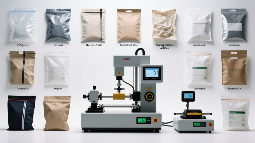
Testing tools and equipment are essential across various industries for ensuring material integrity, performance, and safety. These instruments are categorized based on their specific functions and applications, making it easier to select the right tool for evaluating material properties—especially edge quality, structural integrity, and surface characteristics. Below is a detailed overview of key testing instruments used in industrial and research environments.
Mechanical Slitting Tester
Designed to evaluate the mechanical behavior of materials during slitting processes by applying controlled tensile and bending forces to the edge.
Advantages
- Measures tensile strength and ductility under stress
- Identifies failure points during slitting operations
- Helps improve material durability and product lifespan
- Provides quantitative data for process optimization
Limits
- Primarily focused on edge-specific mechanical stress
- Requires calibrated loading mechanisms
- Less effective for non-metallic or brittle materials
Best for: Metal sheets, polymer films, industrial roll processing, manufacturing QA
Schlieren System
An advanced optical system used to visualize density variations in transparent materials by detecting refractive index changes caused by defects or irregularities.
Advantages
- Highly sensitive to microscopic density variations
- Detects invisible flaws in optical glass and lenses
- Non-contact, non-destructive testing method
- Excellent for quality control in optics manufacturing
Limits
- Limited to transparent or semi-transparent materials
- Requires precise alignment and controlled lighting
- Complex setup and interpretation needed
Best for: Optical components, lens inspection, aerospace glazing, research labs
Optical Microscopes
High-resolution imaging tools used to examine surface topography and edge geometry at microscopic levels using visible light and magnification lenses.
Advantages
- High magnification (up to 1000x) for fine detail analysis
- Real-time visual inspection with color imaging
- Easy to operate and widely available
- Ideal for identifying scratches, grooves, and surface textures
Limits
- Resolution limited by wavelength of light (~200 nm)
- Cannot provide 3D depth profiling without add-ons
- Less effective for sub-micron defect detection
Best for: Surface inspection, quality assurance, metallurgy, education, preliminary edge evaluation
Scanning Electron Microscope (SEM)
A powerful analytical instrument that uses a focused beam of electrons to generate high-resolution, three-dimensional images of material surfaces at the micro and nano scale.
Advantages
- Extremely high resolution (down to 1 nm)
- Produces detailed 3D-like surface topography
- Enables precise roughness and defect analysis
- Can be combined with elemental analysis (EDS)
Limits
- High cost and complex maintenance
- Requires vacuum environment and conductive samples
- Sample preparation can be time-consuming
Best for: Advanced materials research, nanotechnology, failure analysis, precision engineering
Rough Edge Test
A standardized method and device used to quantify edge roughness by comparing measured surface irregularities against international benchmarks (e.g., ISO, ASME).
Advantages
- Provides objective, quantifiable roughness values (Ra, Rz, etc.)
- Available in 2D and 3D profiling versions
- Aligns with global quality standards
- Helps define acceptable surface finish limits
Limits
- Results depend on probe calibration and surface contact
- May miss subsurface or optical defects
- Portable models may lack lab-grade accuracy
Best for: Machined parts, laser-cut edges, automotive components, quality compliance testing
| Instrument | Primary Function | Resolution/Detail | Application Scope | Industry Use |
|---|---|---|---|---|
| Mechanical Slitting Tester | Edge strength & ductility under stress | Macro-level mechanical response | Tensile and bending failure analysis | Manufacturing, Packaging, Materials |
| Schlieren System | Visualize density gradients in transparent media | Sub-micron optical distortion detection | Defect detection in lenses/glass | Optics, Aerospace, R&D |
| Optical Microscope | Surface and edge geometry inspection | Up to ~200 nm resolution | Scratch, groove, texture analysis | QA, Metallurgy, Education |
| Scanning Electron Microscope (SEM) | Ultra-high-resolution surface imaging | Down to 1 nm with 3D capability | Nano-scale roughness and defect mapping | Research, Nanotech, Precision Engineering |
| Rough Edge Test | Quantify edge surface roughness | Standardized Ra/Rz measurements | Compliance with surface finish standards | Automotive, Machining, Quality Control |
Expert Tip: For comprehensive edge quality assessment, combine multiple testing methods—such as using an optical microscope for initial inspection, followed by SEM for detailed analysis and a roughness tester for quantitative validation. This multi-instrument approach ensures both qualitative and quantitative accuracy.
Important Features of Test and Measurement Devices for Edge Smoothness
Test and measurement devices play a vital role in evaluating material quality, particularly in assessing edge smoothness across industrial, manufacturing, and research applications. The effectiveness of these instruments depends on several key features—such as sensitivity, precision, standoff distance, and quantification capabilities—that directly influence accuracy, repeatability, and usability. Understanding these features enables engineers and quality control professionals to select the most appropriate technology for their specific needs.
Sensitivity and Precision in Edge Analysis
Sensitivity and precision are foundational metrics in determining the reliability of edge smoothness measurements. High sensitivity allows instruments to detect minute surface irregularities, while precision ensures consistent and repeatable results across multiple tests.
Scanning Electron Microscopy (SEM)
SEM is renowned for its exceptional sensitivity, capable of magnifying edge surfaces up to one million times. This level of magnification reveals nanoscale features such as micro-fractures, burrs, and grain boundaries that are invisible to optical systems. Its high precision makes it ideal for advanced materials research, semiconductor manufacturing, and aerospace component inspection.
Optical Microscopy and Slitting Testers
While optical microscopes offer lower magnification—typically up to 2000x—they provide non-destructive, real-time imaging suitable for routine quality checks. Slitting testers complement these systems by measuring force and deformation with high accuracy, enabling the detection of subtle variations in tensile strength and bending behavior. These tools are widely used in metal fabrication and packaging industries where edge integrity affects performance.
Given that edge smoothness often hinges on microscopic anomalies, the choice between SEM and optical methods should be guided by required resolution, sample type, and operational constraints.
Standoff Distance and Its Impact on Resolution
Standoff distance—the space between the measurement probe or lens and the specimen surface—significantly affects image clarity and system safety. Shorter standoff distances generally allow for higher resolution imaging, making them critical in high-precision applications.
SEM: Nanometer-Scale Proximity
SEMs operate with a standoff distance of just a few nanometers, enabling unparalleled resolution of fine surface textures. This proximity allows for detailed 3D reconstructions of edge profiles, making SEM the gold standard for scientific and industrial edge quality assessment. However, this requires vacuum environments and conductive coatings, limiting its use with certain materials.
Optical Microscopes: Greater Working Distance
In contrast, optical microscopes maintain a standoff distance exceeding 200 microns, offering greater flexibility for live or in-situ measurements. While this reduces maximum resolution, it enables safer inspection of delicate, non-conductive, or heat-sensitive samples without preparation. This makes optical systems preferable for production-line monitoring and educational settings.
The trade-off between resolution and practicality underscores the importance of selecting a system based on application-specific requirements rather than raw performance alone.
Rough Edge Test Devices: Automation and Quantitative Analysis
Modern rough edge test devices streamline the evaluation process through automation and standardized procedures. These instruments eliminate subjective visual assessments by providing objective, data-driven results.
These capabilities make rough edge testers invaluable in industries such as automotive, medical device manufacturing, and precision machining, where edge finish directly impacts safety, performance, and regulatory compliance.
Edge Smoothness Instruments: From Qualitative to Quantitative Evaluation
Historically, edge smoothness assessment relied heavily on qualitative methods—such as visual inspection or tactile comparison—which are prone to inconsistency and interpretation bias. However, modern instrumentation has shifted toward quantitative analysis, offering measurable, repeatable insights into edge characteristics.
Quantification provides concrete metrics such as surface roughness average (Ra), peak-to-valley height (Rt), and waviness, which correlate directly with functional performance. For example:
- A smoother edge (low Ra value) reduces friction and wear in moving parts.
- Controlled edge roughness can enhance adhesion in coating or bonding processes.
- Excessive burrs or micro-cracks can compromise structural integrity in load-bearing components.
By assigning numerical values to edge profiles, manufacturers can establish quality benchmarks, optimize machining parameters, and ensure compliance with industry standards such as ISO 4287 or ASME B46.1. This transition from subjective to objective evaluation represents a major advancement in quality assurance and process control.
| Feature | Importance | Best Suited For |
|---|---|---|
| Sensitivity (Magnification) | High | SEM for nanoscale defects; optical for macro-level inspection |
| Precision & Repeatability | High | Quality control, R&D, certification processes |
| Standoff Distance | Medium-High | SEM for max resolution; optical for non-contact safety |
| Quantitative Output | High | Automated production, regulatory compliance, data logging |
| Automation Level | Medium | High-volume testing, operator-independent results |
Important: Selecting the right test and measurement device requires balancing technical capabilities with practical considerations such as cost, sample preparation, and integration into existing workflows. Always validate instrument performance using certified reference materials and adhere to calibration schedules to maintain measurement integrity. Investing in quantifiable, high-resolution systems pays long-term dividends in product quality, process efficiency, and customer satisfaction.
Commercial Use Scenarios
Edge smoothness is a critical quality parameter across multiple industries, influencing performance, safety, durability, and precision. Rigorous testing and assessment ensure that materials meet exacting standards before deployment. Below are key commercial applications where edge smoothness plays a vital role in product integrity and operational efficiency.
Slitting Edge Smoothness in the Automotive Industry
In automotive manufacturing, edge smoothness is not only essential for aesthetic appeal but also for functional and safety performance. Components with smooth, burr-free edges enhance vehicle aerodynamics, reduce air resistance, and minimize wear caused by friction between moving parts.
- Sharp or jagged edges on stamped metal parts can compromise worker safety during assembly and maintenance
- Smoothly finished edges on body panels and structural components prevent premature corrosion and paint adhesion issues
- High-speed production lines rely on consistent edge quality to maintain downstream process efficiency
- Automotive suppliers use profilometers and optical comparators to verify edge finish compliance with OEM specifications
Best practice: Implement automated edge inspection systems in production to detect micro-burrs and surface irregularities early.
Aerospace Applications
The aerospace industry enforces some of the strictest tolerances for edge smoothness due to the extreme operating conditions of aircraft and spacecraft. Even minor edge defects can lead to stress concentrations, fatigue cracking, or catastrophic failure under high pressure and temperature fluctuations.
- Smooth edges on turbine blades, wing components, and fuselage panels reduce drag and improve fuel efficiency
- Burr-free machining of aluminum and titanium alloys is critical to prevent contamination in hydraulic and fuel systems
- Regulatory standards such as AS9100 and NADCAP require documented edge inspection and certification
- Laser scanning and tactile measurement tools are used to validate edge radii and surface finish on safety-critical parts
Critical insight: A single unpolished edge in a jet engine assembly can initiate crack propagation under cyclic loading.
Electronics Manufacturing
In the electronics sector, edge smoothness directly affects the reliability and functionality of sensitive components. Microscopic imperfections along cut or etched edges can create electrical leakage paths, increase resistance, or cause short circuits.
- Printed circuit boards (PCBs) require clean, smooth cut edges to avoid delamination and ensure proper solder adhesion
- Semiconductor wafers undergo precision dicing with diamond blades to maintain edge integrity and prevent chipping
- Sharp edges on connectors or shielding components can damage adjacent insulation or circuitry during assembly
- Automated optical inspection (AOI) systems detect edge flaws in high-volume production environments
Quality tip: Use non-contact measurement techniques like interferometry for fragile electronic substrates.
Optical Technologies
Optical devices demand near-perfect edge smoothness to maintain light transmission, minimize scattering, and preserve image clarity. Any surface defect—even at the micron level—can distort optical performance in lenses, prisms, fiber optics, and sensors.
- Fiber optic terminations require flawlessly polished ends to reduce signal loss and back reflection
- Microscope and camera lenses undergo edge grinding and lapping to eliminate micro-cracks and subsurface damage
- Rough edges on optical glass can act as nucleation points for fractures under thermal or mechanical stress
- Manufacturers use atomic force microscopy (AFM) and white-light interferometry for nanoscale edge analysis
Precision note: Optical components often require surface finishes below 10 nm Ra (roughness average) for optimal performance.
Metalworking and General Manufacturing
In metal fabrication, edge smoothness is a key indicator of machining quality and directly impacts the strength, fit, and longevity of finished products. Processes such as laser cutting, stamping, shearing, and grinding all influence edge characteristics.
- Roughness, edge radius, and burr height are standard metrics measured using profilometers and vision systems
- Deburring and edge rounding operations (e.g., tumbling, brushing, or electropolishing) are applied to improve safety and performance
- Structural components in construction and machinery require smooth transitions to reduce stress concentration
- Automotive stampings, HVAC ducts, and appliance housings are routinely inspected for edge quality
Industry standard: ISO 1302 and ASME Y14.5 provide guidelines for surface texture and geometric dimensioning, including edge specifications.
Expert Recommendation: Across all industries, integrating edge smoothness testing into quality control protocols ensures consistency, reduces field failures, and enhances customer satisfaction. Investing in calibrated measurement equipment and operator training leads to long-term cost savings and improved product reliability. For high-precision applications, consider partnering with certified metrology labs for periodic validation.
| Industry | Primary Concern | Common Testing Method | Typical Tolerance (Ra/Edge Radius) |
|---|---|---|---|
| Automotive | Safety, aerodynamics, corrosion resistance | Profilometry, visual inspection | 0.8–3.2 μm Ra |
| Aerospace | Structural integrity, fatigue resistance | Laser scanning, tactile probes | 0.2–1.6 μm Ra / 0.1–0.5 mm radius |
| Electronics | Electrical isolation, component reliability | Optical microscopy, AOI | <1.0 μm Ra (PCBs), sub-micron edge control |
| Optical Technologies | Light transmission, image clarity | Interferometry, AFM | <0.1 μm Ra (polished surfaces) |
| Metalworking | Durability, fitment, operator safety | Surface roughness testers, go/no-go gauges | 1.6–6.3 μm Ra (general), burr height <0.1 mm |
Additional Considerations
- Automation Integration: Edge inspection systems are increasingly integrated into CNC machines and robotic cells for real-time quality feedback
- Environmental Impact: Smoother edges reduce particulate generation during operation, improving workplace air quality
- Cost of Non-Conformance: Poor edge quality can lead to recalls, warranty claims, and reputational damage, especially in regulated industries
- Material-Specific Challenges: Different materials (e.g., composites, brittle ceramics, soft polymers) require tailored edge finishing and measurement approaches
- Documentation & Traceability: Maintaining records of edge inspections supports compliance with ISO, FDA, and aerospace quality standards
How to Choose Testing Instruments and Equipment for Edge Smoothness Evaluation
Selecting the right testing instruments and equipment is a critical decision that directly impacts product quality, compliance, and operational efficiency. Whether you're in manufacturing, aerospace, automotive, or construction, accurate edge smoothness assessment ensures durability, safety, and performance. This comprehensive guide provides actionable insights to help businesses make informed decisions when purchasing edge smoothness testing equipment, covering key considerations such as application needs, technical specifications, accuracy, regulatory compliance, and cost-effectiveness.
Important Note: Choosing the wrong testing instrument can lead to inconsistent measurements, product defects, regulatory non-compliance, and increased long-term costs. Always align equipment selection with your specific operational requirements and quality standards.
1. Assess Your Specific Needs
Before investing in any testing equipment, it's essential to evaluate your unique operational context. The ideal instrument depends on several factors including business scale, material types, production volume, and industry-specific applications.
- Business Size: Large-scale manufacturers with high-volume production lines benefit from automated, high-precision systems that integrate with quality control workflows. Smaller operations may find cost-effective, manual testers sufficient for periodic inspections.
- Material Type: Different materials—such as metals, composites, ceramics, or polymers—require tailored measurement approaches. For example, softer materials may need lower contact force to avoid surface deformation during testing.
- Industry Application: Aerospace and medical device manufacturing demand extreme precision due to safety-critical components, whereas general fabrication may allow for broader tolerances.
- Future Scalability: Consider potential growth. Instruments that support software upgrades, additional probes, or data integration can save costs over time compared to replacing outdated systems.
Pro Tip: Create a checklist of your must-have features (e.g., portability, digital output, ease of calibration) before speaking with vendors. This helps streamline comparisons and prevents overspending on unnecessary capabilities.
2. Evaluate Edge Roughness Tester Hardware Specifications
The hardware capabilities of a roughness tester determine its suitability for your application. Key technical parameters should be carefully reviewed to ensure reliable and meaningful results.
- Measurement Range: Ensure the instrument can measure both fine finishes (e.g., Ra 0.025 µm) and coarser surfaces (up to Ra 12.5 µm or higher), depending on your materials.
- Resolution: High-resolution sensors (down to 0.001 µm) are essential for detecting subtle variations in edge quality, especially in precision engineering.
- Stylus Tip Radius: A smaller radius (e.g., 2 µm) captures fine surface details but may wear faster. Larger tips (5–10 µm) are more durable but may miss micro-defects.
- Tracing Length and Cutoff Wavelength: These settings affect how surface texture is analyzed. Adjustable cutoffs allow compliance with various international standards (e.g., ISO 4287, ASME B46.1).
- Data Output and Connectivity: Modern testers often include USB, Bluetooth, or Wi-Fi for exporting data to QA software, enabling traceability and statistical process control (SPC).
Misclassification of edge roughness—either underestimating or overestimating surface finish—can result in functional failures, increased wear, or rejection during audits. Selecting a device with appropriate technical power minimizes these risks.
3. Prioritize Accuracy and Precision
In edge smoothness testing, even micrometer-level deviations can significantly affect component performance, particularly in high-friction or sealing applications. Therefore, selecting instruments with high accuracy and repeatability is non-negotiable.
- Accuracy: Refers to how close the measurement is to the true value. Look for instruments calibrated to national or international standards (e.g., NIST-traceable certification).
- Repeatability: The ability to produce consistent results under the same conditions across multiple tests. A repeatability specification of ±2% or better is recommended for quality-critical environments.
- Reproducibility: Consistent results across different operators, environments, or time periods. Devices with guided measurement modes and automatic stylus positioning improve reproducibility.
- Environmental Compensation: Advanced models include temperature compensation and vibration damping to maintain accuracy in industrial settings.
Consistent, reliable data supports robust quality management systems (QMS), reduces scrap rates, and enhances customer confidence in your products.
Expert Insight: Conduct a side-by-side comparison of two or three shortlisted instruments using a known reference sample. This practical test reveals real-world performance differences not evident from datasheets alone.
4. Ensure Regulatory and Industry Compliance
Testing instruments must comply with relevant industry standards to ensure validity, legal defensibility, and market acceptance of your quality data.
- Semiconductor & Electronics: Often require compliance with ISO 25178 (areal surface texture) and SEMI standards.
- Aerospace & Automotive: Follow AS9100 and IATF 16949, which mandate use of calibrated, documented measurement systems.
- Construction & Composites: May adhere to national standards such as ASTM E975 or DIN 4768, depending on region and application.
- Medical Devices: Require FDA-compliant documentation and adherence to ISO 13485 quality management requirements.
Non-compliant equipment can invalidate test reports, lead to failed audits, or result in product recalls. Always verify that the instrument comes with a calibration certificate and supports required reporting formats.
Warning: Using non-certified or uncalibrated equipment may expose your business to legal liability, especially in regulated industries. Regular recalibration (typically annually) is essential to maintain compliance.
5. Balance Budget and Long-Term Cost of Ownership
While initial purchase price is important, it should not be the sole deciding factor. A comprehensive cost-benefit analysis should include long-term operational expenses and return on investment (ROI).
| Instrument Tier | Typical Cost Range | Key Features | Best For |
|---|---|---|---|
| Entry-Level | $500 – $2,000 | Basic analog/digital readout, single-parameter measurement, manual operation | Small workshops, infrequent use, educational purposes |
| Mid-Range | $2,000 – $8,000 | Digital display, multiple parameters (Ra, Rz, Rq), data logging, PC connectivity | Medium manufacturers, routine QC, ISO-compliant environments |
| Premium/Industrial | $8,000 – $20,000+ | Automated stages, 3D surface mapping, SPC integration, NIST-traceable calibration | High-precision industries (aerospace, medical, semiconductor) |
Cheap instruments may only measure a single parameter (e.g., Ra) and lack data storage, while advanced systems offer multi-parameter analysis, trend tracking, and integration with enterprise quality systems. Consider:
- Cost of calibration and maintenance
- Availability of spare parts and technical support
- Training requirements for operators
- Software update policies and lifespan
The most cost-effective choice balances upfront investment with functionality, durability, and compliance needs.
Value Tip: Leasing or renting high-end equipment for short-term projects can be more economical than purchasing. Some suppliers also offer trade-in programs for upgrading older models.
Final Recommendations
- Always request a demonstration or trial unit before purchase.
- Verify warranty terms (minimum 1 year recommended) and availability of local service centers.
- Choose instruments with intuitive interfaces to reduce operator error.
- Ensure compatibility with existing quality documentation systems.
- Train personnel on proper usage and care to extend equipment life and ensure data integrity.
Investing in the right edge smoothness testing instrument is not just about buying hardware—it's about ensuring product excellence, regulatory compliance, and customer satisfaction. By carefully evaluating your needs, technical requirements, and total cost of ownership, you can make a confident, future-ready decision that supports your quality goals for years to come.
Frequently Asked Questions About Edge Smoothness Measurement
Q1: Are edge smoothness instruments necessary for all industries?While edge smoothness instruments are not universally required across every industry, they play a critical role in sectors where precision, performance, and safety are paramount. When edge quality is not properly assessed and controlled, it can lead to a range of issues including mechanical failure, increased wear, reduced product lifespan, and potential safety hazards.
Industries that work with thin materials, micro-components, or high-precision parts—such as aerospace, medical device manufacturing, electronics, and automotive engineering—typically rely on edge smoothness testing to ensure product integrity. In contrast, industries dealing with bulk materials or less sensitive applications may not prioritize edge measurement. Therefore, while not essential for every sector, edge smoothness instruments are indispensable in many advanced manufacturing and technology-driven fields.
Q2: What is edge roughness, and why is it important?Edge roughness refers to the microscopic irregularities in height and texture along the perimeter of a material’s cut edge. It is a key indicator of surface finish quality and is primarily quantified using the Ra (Roughness Average) value—the arithmetic average of surface deviations from the mean plane over a given measurement length.
The Ra value provides a standardized way to assess surface texture and directly influences several critical performance factors:
- Friction & Wear: Smoother edges reduce friction, minimizing wear in moving components and extending service life.
- Sealing Performance: In fluid or gas systems, rough edges can compromise seals, leading to leaks.
- Structural Integrity: High roughness can act as stress concentrators, increasing the risk of crack initiation and material failure.
- Aesthetic & Functional Fit: Especially in consumer electronics or medical implants, smooth edges are vital for both appearance and biocompatibility.
Accurate measurement of edge roughness ensures components meet functional, safety, and regulatory requirements.
Q3: What are some common standards for edge smoothness?Various international and industry-specific standards govern edge smoothness measurement, ensuring consistency and reliability across manufacturing processes. These standards define acceptable roughness levels, measurement techniques, and evaluation criteria. Key standards include:
| Standard | Origin | Primary Industries | Key Parameters Measured |
|---|---|---|---|
| ISO 4287 / ISO 4288 | International Organization for Standardization | Semiconductors, Electronics, Precision Engineering | Ra, Rz, surface waviness, profile filtering |
| ANSI B46.1 | American National Standards Institute | General Manufacturing, Aerospace, Automotive | Surface texture, roughness, lay, and flaws |
| VDA 231-10 | German Association of the Automotive Industry | Automotive (especially German OEMs) | Edge roughness, burr height, edge rounding |
| EUSA (European Sheet Metal Standard) | European Union Sheet Metal Association | Sheet metal fabrication, industrial equipment | Edge quality classes, defect tolerance, Ra limits |
These standards not only define acceptable roughness values but also specify the instruments and methodologies—such as profilometers or optical comparators—used for evaluation. Consistent application of these standards ensures interoperability, quality control, and compliance with global manufacturing norms.
Q4: What factors influence edge smoothness in materials?Edge smoothness is influenced by a combination of manufacturing processes and material characteristics. The two primary factors are:
1. Manufacturing Process
The method used to cut or shape the material has a direct impact on edge finish:
- Mechanical Slitting or Shearing: Can produce small burrs and micro-tears, resulting in moderate roughness (higher Ra values).
- Laser Cutting: Offers high precision with minimal contact, typically yielding smoother edges and lower Ra values.
- Waterjet Cutting: Produces clean edges with little thermal distortion, though surface texture depends on abrasive type and pressure.
- Electro-Discharge Machining (EDM): Ideal for hard materials, but may leave a recast layer affecting surface integrity.
- Grinding or Polishing: Used post-processing to refine edges and achieve ultra-smooth finishes for high-tolerance applications.
2. Material Properties
The physical and structural characteristics of the material also affect edge quality:
- Density & Hardness: Harder materials like tool steels may resist deformation but are more prone to chipping during cutting.
- Microstructure: Grain size and homogeneity influence how cleanly a material separates during cutting.
- Ductility vs. Brittleness: Ductile materials (e.g., copper) may form burrs, while brittle materials (e.g., ceramics) are prone to cracking.
- Composite Layers: Multi-material laminates (e.g., aluminum-plastic composites) can delaminate at edges if not processed carefully.
Optimizing both process parameters and material selection is essential for achieving desired edge smoothness in precision manufacturing.
Q5: Are there any recent developments in edge smoothness standards?Yes, edge smoothness standards are evolving rapidly in response to technological advancements and emerging industry demands. As materials and applications become more complex, traditional metrics are being refined and expanded to address new challenges:
- Composite Materials: With growing use of carbon fiber-reinforced polymers (CFRP) and hybrid laminates in aerospace and automotive sectors, new standards are being developed to assess edge quality in multi-phase materials. ISO and ASTM are actively working on guidelines for delamination, fiber pull-out, and interlayer integrity.
- Nanomaterials & Micro-Systems: In MEMS (Micro-Electro-Mechanical Systems) and nanotechnology, edge smoothness at the sub-micron level is critical for functionality. New measurement protocols using atomic force microscopy (AFM) and scanning electron microscopy (SEM) are being integrated into updated standards.
- Digital Metrology: Advances in 3D surface mapping and AI-driven image analysis are enabling more accurate and automated edge assessments. Standards are now incorporating digital calibration and traceability requirements.
- Sustainability & Reusability: Some industries are adopting edge quality benchmarks that support longer component life and recyclability, reducing waste and environmental impact.
Organizations like ISO, ASME, and VDA are continuously revising their documentation to reflect these innovations, ensuring that edge smoothness remains a reliable predictor of performance and durability in next-generation technologies.