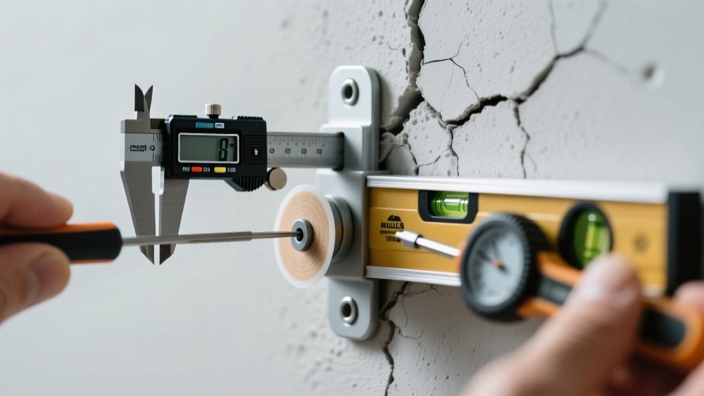
Selecting a U clamp solar mount isn’t about finding the cheapest or flashiest option—it’s about engineering confidence. These unassuming clamps anchor your entire photovoltaic array to the roof structure, transferring wind uplift, snow load, and thermal expansion forces into the building’s frame. A single underspecified or improperly installed U clamp can compromise system integrity, void warranties, and create long-term liability. Yet many installers treat them as commodity hardware, leading to field adjustments, rework, and premature failures. This guide cuts through marketing claims and focuses on verifiable performance criteria—grounded in structural principles, real-world weather exposure, and decades of field data from commercial and residential solar deployments across North America and Europe.
Understand What a U Clamp Actually Does—Beyond “Holding Panels”
A U clamp is a structural interface—not just a fastener. It bridges two critical systems: the solar module’s aluminum frame (typically with T-slots or mounting holes) and the roof’s underlying support—usually purlins, rafters, or standing seam profiles. Its primary mechanical functions are:
- Load transfer: Redirecting lateral wind forces (uplift and shear) into the roof’s primary framing;
- Thermal accommodation: Allowing controlled movement between dissimilar metals (e.g., aluminum modules and steel purlins) without inducing stress fractures;
- Compression control: Applying consistent, non-damaging clamping force to prevent frame deformation while maintaining electrical grounding continuity;
- Corrosion isolation: Preventing galvanic reactions between dissimilar metals through intentional dielectric separation.
When a U clamp fails, it rarely snaps dramatically. More often, it exhibits slow creep under cyclic loading—gradual loosening over seasons, micro-galling at contact surfaces, or localized corrosion that reduces cross-sectional strength by 30% or more before visual inspection detects anything. That’s why selection must begin with load calculations—not catalog browsing.
Step-by-Step: Load Verification Before You Specify Any Clamp
- Determine local design wind speed and exposure category (ASCE 7-22 or CSA A23.3 for Canada). Use tools like NOAA’s Wind Speed Maps or your jurisdiction’s building code appendix—not generic “120 mph” assumptions.
- Calculate uplift and shear forces per module using your racking manufacturer’s wind tunnel report. Never rely on generic tables; forces vary by array height, edge vs. field position, and roof slope.
- Confirm purlin/rafter spacing and material specs. A 14-gauge steel purlin spaced at 5’ o.c. carries less load than a 12-gauge at 4’ o.c.—and wood rafters require different clamping torque protocols entirely.
- Select clamps rated for *actual* applied loads—not just “max module width.” For example, a clamp rated for “up to 1,200 lbs uplift” may only deliver 820 lbs when mounted to 16-gauge steel with #12 self-drilling screws.
- Verify torque retention after thermal cycling. Request third-party test reports showing clamp performance after 200 cycles between −40°C and +85°C—standard industry practice for Tier 1 manufacturers.
Material Integrity: Why Not All Stainless Steel Is Equal
The phrase “stainless steel” appears on 90% of U clamp spec sheets—but ASTM grades differ drastically in chloride resistance, tensile strength, and cold-work hardening behavior. Here’s what matters:
| Grade | Tensile Strength (MPa) | Key Limitation | Recommended Use Case |
|---|---|---|---|
| 304 Stainless | 515–620 | Poor resistance to salt spray and industrial pollutants; prone to pitting in coastal zones | Inland residential projects, low-humidity climates, non-coastal commercial |
| 316 Stainless | 515–620 | Higher molybdenum content resists chlorides—but still vulnerable to crevice corrosion if gasketing fails | Coastal installations, marine environments, high-salt road exposure |
| 17-4PH Precipitation-Hardened | 1,200–1,400 | Requires strict heat-treatment control; not suitable for field welding | High-wind commercial roofs, hurricane-prone regions, rooftop carports |
| Aluminum 6061-T6 | 310 | Must be isolated from steel/iron substrates to prevent galvanic corrosion | Standing seam metal roofs, lightweight structures where weight is critical |
Crucially, the clamp body is only half the equation. Bolts, washers, and nuts must match or exceed the base material’s corrosion class. A 316 clamp paired with 304 bolts defeats the purpose—the weaker alloy will corrode first, initiating failure at the most highly stressed point.
Real-World Example: The Houston Warehouse Retrofit
In 2022, a logistics facility in Houston installed a 1.2 MW rooftop array using a budget-tier U clamp advertised as “marine-grade stainless.” Within 18 months, 14% of clamps showed visible white corrosion powder at the bolt head-to-clamp interface. Third-party metallurgical analysis revealed the bolts were 304 stainless, while the clamp bodies were genuine 316—but the mismatch created a galvanic cell accelerated by daily condensation and airborne sulfur compounds from nearby refineries. Replacement cost exceeded $87,000, plus downtime penalties. The fix? Swapping to fully matched 316 assemblies with EPDM isolators and torque-controlled installation—verified by ultrasonic bolt tension testing. As project engineer Lena Torres noted: “We saved $0.12/W upfront—and paid $0.73/W in remediation. Load ratings mean nothing if the system isn’t chemically coherent.”
Roof Compatibility: Standing Seam vs. Through-Bolt vs. Structural Attachment
U clamps aren’t one-size-fits-all. Their design must align precisely with how your roof transfers load:
- Standing seam clamps grip the vertical leg of the seam—not the cap. They require precise seam profile matching (e.g., Berridge 2” Snap-Loc vs. MBCI 1.5” Double-Lock). Misalignment causes point loading and seam deformation.
- Through-bolt clamps penetrate the roof panel and anchor directly to the purlin below. Critical factors: drill bit tolerance (±0.005”), washer diameter (must exceed panel embossing), and sealant compatibility with the roof coating (e.g., Kynar 500 vs. PVDF).
- Structural attachment clamps bypass the roof panel entirely, bolting to exposed purlin flanges or welded brackets. Used on built-up roofs (BUR) or concrete decks. Requires verified purlin flange thickness and bolt hole alignment.
“Clamp selection starts at the roof drawing—not the solar layout. If you don’t know the purlin gauge, spacing, and substrate material before ordering clamps, you’re guessing. And guessing costs money, time, and reputation.” — Rajiv Mehta, P.E., Senior Structural Engineer, SolDesign Engineering Group
Corrosion Resistance: Beyond the Spec Sheet
Manufacturers list “salt spray rating” (ASTM B117) as hours to first red rust—often 1,000+ hours. But real-world corrosion isn’t uniform. It’s driven by three co-occurring factors:
- Electrolyte presence: Condensation, acid rain, de-icing salts, or even bird droppings create conductive paths.
- Galvanic potential difference: Aluminum modules + steel purlins + stainless clamps = a battery. Dielectric isolation (EPDM, silicone, or nylon washers) must cover *all* contact surfaces—not just the clamp-to-purlin interface.
- Mechanical damage: Over-torquing scratches protective oxide layers. Under-torquing allows micro-motion that abrades coatings. Torque must be validated with calibrated tools—not “snug plus quarter-turn.”
Look for clamps with integrated isolation—no field-applied tape or grease. Also verify that the isolation material withstands UV exposure (ASTM G154) and maintains dielectric strength (>500 V/mil) after 10 years of thermal cycling.
Installation Essentials Checklist
- ✅ Confirm purlin/rafter location via stud finder *and* physical probe—never rely on roof plans alone.
- ✅ Use torque-controlled drivers set to the clamp manufacturer’s exact specification (e.g., 22 ± 1 N·m)—not impact drivers or “feel.”
- ✅ Install all clamps in the same orientation (e.g., bolt heads facing array center) to ensure uniform thermal expansion behavior.
- ✅ Verify grounding continuity (<25 ohms) between each clamp and the main bonding conductor *before* module installation.
- ✅ Document torque verification with photos and digital logs for warranty compliance.
FAQ
Can I reuse U clamps from a decommissioned array?
No—unless they’ve undergone full non-destructive testing (NDT) including dye penetrant inspection, thread gauging, and torque retention validation. Stress corrosion cracking is invisible to the naked eye and accelerates after first use. Reuse violates UL 2703 and most manufacturer warranties.
Do I need different clamps for ballasted versus penetrated systems?
Yes. Ballasted systems rely on clamp friction and mass inertia—requiring higher clamping force and wider base plates. Penetrated systems transfer load directly into structure, allowing slimmer profiles but demanding higher bolt shear strength. Never substitute one for the other without engineering sign-off.
Why do some clamps specify “for aluminum frames only”?
Steel or composite module frames have different flexural modulus and thermal expansion coefficients. Clamps designed for aluminum may over-constrain steel frames, causing micro-cracks in junction boxes or frame welds during temperature swings. Always match clamp specifications to your module’s frame material and certification (IEC TS 62788-7-2).
Conclusion
Choosing the best U clamp solar mount is an act of quiet professionalism—where attention to metallurgy, structural physics, and environmental chemistry separates durable, warrantable installations from costly liabilities. It means reading test reports instead of brochures, verifying purlin specs before ordering, and treating torque like a calibrated measurement—not a suggestion. The strongest array isn’t the one with the thickest rails or highest wattage panels. It’s the one anchored with components selected, installed, and documented with uncompromising precision. Your roof, your client’s investment, and your reputation depend on it. Don’t settle for “good enough.” Demand traceable performance, chemical coherence, and verified load paths—every time.
💬 Have you encountered a U clamp failure—or a standout success? Share your experience, lessons learned, or field-tested tips in the comments. Real-world insights help raise standards across our industry.