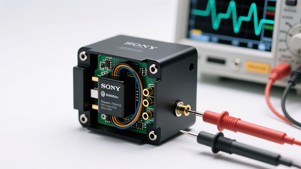
Types of Electric Power Factor Testers
An electric power factor tester is an essential diagnostic tool used to measure the efficiency of electrical power usage in industrial, commercial, and utility systems. The power factor—defined as the ratio of real power to apparent power—indicates how effectively electricity is being utilized. A low power factor can lead to energy waste, increased utility costs, and equipment stress. These testers come in various configurations designed to meet different operational needs, environments, and precision requirements.
Understanding the different types of power factor testers helps technicians, engineers, and maintenance teams select the right tool for accurate monitoring, preventive maintenance, and compliance with energy efficiency standards.
Manual Electric Power Factor Tester
Compact, handheld devices that require user input for readings and data recording. Ideal for field use where automation isn't necessary.
Advantages
- Portable and lightweight
- No external power source required
- Cost-effective for basic diagnostics
- Simple interface for quick measurements
Limitations
- Requires manual data logging
- Limited data storage and analysis
- Higher chance of human error
- Not ideal for continuous monitoring
Best for: Field technicians, small-scale installations, remote locations with limited infrastructure
Electric Power Factor Meter (Automated)
Advanced digital meters that automatically record, compute, and display real-time power factor data with minimal user intervention.
Advantages
- Real-time data acquisition and display
- High accuracy and repeatability
- Integrated data logging and reporting
- Compatible with SCADA and monitoring systems
Limitations
- Higher initial cost
- Requires stable power supply
- More complex setup and calibration
- Bulkier than manual models
Best for: Industrial plants, data centers, facilities requiring continuous power quality monitoring
Low Power Factor Indicator
Specialized devices designed to detect and alert on lagging power factors, often integrated into automatic correction systems.
Advantages
- Triggers automatic capacitor bank activation
- Prevents equipment overheating
- Reduces energy losses and utility penalties
- Protects motors, transformers, and generators
Limitations
- Limited to detection, not full diagnostics
- May require integration with external systems
- Less useful in systems with already optimized power factor
Best for: Power correction panels, industrial automation, facilities with fluctuating reactive loads
High Voltage Electric Power Factor Meter
Engineered for safe and precise operation in high-voltage environments such as transmission lines, substations, and switchgear.
Advantages
- Operates safely at voltages up to 500 kV+
- Meets international calibration standards (IEC, IEEE)
- Used for preventive maintenance of HV equipment
- Essential for transformer and cable insulation testing
Limitations
- Expensive and specialized equipment
- Requires trained personnel for operation
- Bulky and less portable
- Needs strict safety protocols
Best for: Utility companies, high-voltage substations, transformer testing, compliance verification
Insulation Resistance Tester with Power Factor Measurement
Dual-function testers that assess both insulation integrity and power factor, providing comprehensive diagnostics for electrical assets.
Advantages
- Combines two critical tests in one device
- Early detection of insulation degradation
- Improves predictive maintenance accuracy
- Reduces downtime and repair costs
Limitations
- Higher cost than single-function testers
- Requires proper training for interpretation
- Test duration may be longer due to combined procedures
Best for: Preventive maintenance, transformer testing, motor insulation checks, utility infrastructure audits
| Tester Type | Primary Function | Accuracy Level | Application Environment | Ideal Use Case |
|---|---|---|---|---|
| Manual Electric Power Factor Tester | Basic power factor measurement | Moderate | Field, small installations | Remote diagnostics, spot checks |
| Automated Electric Power Factor Meter | Continuous real-time monitoring | High | Industrial, commercial | Energy management, process optimization |
| Low Power Factor Indicator | Detection and alerting | Medium | Control panels, automation | Automatic correction systems |
| High Voltage Power Factor Meter | Precision HV testing | Very High | Substations, transmission | Transformer and cable diagnostics |
| Insulation + Power Factor Tester | Dual diagnostic testing | High | Maintenance, utilities | Predictive maintenance programs |
Expert Tip: For high-voltage applications, always follow safety protocols including proper grounding, use of PPE, and lockout/tagout procedures when operating power factor testers. Regular calibration ensures measurement accuracy and compliance with industry standards like IEEE 62 and IEC 60270.
Function, Features, and Design of Electric Power Factor Testers
Electric power factor testers are essential diagnostic tools used in electrical engineering and industrial maintenance to assess the efficiency of power usage in electrical systems. By measuring the ratio of real power (kW) to apparent power (kVA), these devices help identify energy waste, reduce electricity costs, and improve system reliability. Understanding their function, features, and design enables technicians and engineers to make informed decisions for optimizing electrical performance.
Core Functions of Electric Power Factor Testers
Power factor testers perform a range of critical functions that support energy efficiency and system diagnostics. These tools go beyond simple measurement—they provide actionable insights into the health and performance of electrical installations. Key functions include:
Accuracy in Measurements
High-precision sensors and advanced signal processing ensure reliable and repeatable readings. Accurate power factor measurements allow users to detect inefficiencies such as reactive power buildup, which can lead to increased utility bills and equipment stress. This precision is vital in industrial settings where even small improvements in power factor can yield significant cost savings.
Real-time Monitoring
Modern power factor testers offer live display of electrical parameters, enabling immediate response to fluctuating loads or poor power quality. Real-time feedback supports dynamic adjustments to capacitor banks or load distribution, helping maintain optimal power factor levels and prevent penalties from utility providers.
Multiple Parameter Testing
These testers simultaneously measure voltage, current, frequency, active/reactive/apparent power, harmonics, and power factor. This comprehensive data collection provides a full picture of system performance, making them invaluable for troubleshooting, commissioning, and preventive maintenance of motors, transformers, and distribution panels.
Data Logging and Analysis
Advanced models include internal memory or SD card support to record measurements over time. This data logging capability supports trend analysis, load profiling, and compliance reporting. It's particularly useful for identifying cyclical inefficiencies and planning energy-saving upgrades or capacitor installations.
Key Features Enhancing Performance and Usability
Beyond core functionality, electric power factor testers are equipped with intelligent features designed to improve efficiency, accuracy, and user experience in diverse environments—from industrial plants to remote field sites.
Innovative Design Elements for Durability and Ergonomics
The physical design of power factor testers reflects the demanding conditions in which they operate. From factory floors to outdoor substations, these instruments must be robust, user-friendly, and adaptable to various testing scenarios.
Rugged Construction
Housed in impact-resistant ABS plastic or reinforced polymer casings, these testers withstand drops, vibrations, and harsh environments. Internal components are often conformal-coated to resist moisture and dust ingress, ensuring long-term reliability in industrial settings.
Ergonomic Grips
Soft-touch, contoured grips reduce hand fatigue during extended use. The balanced weight distribution and non-slip surfaces enhance control, especially when working with clamp probes or in confined electrical panels.
Compact Size
Designed for mobility and access, many testers fit comfortably in tool belts or instrument cases. Their small footprint allows use in tight switchgear cabinets or crowded control rooms, improving workflow efficiency during maintenance rounds.
Water and Dust Resistance
Rated to IP54 or higher, most modern testers resist splashing water and airborne dust. This makes them suitable for outdoor use, wet environments, or dusty industrial zones, ensuring consistent performance regardless of site conditions.
| Feature | Benefit | Typical Use Case |
|---|---|---|
| High Measurement Accuracy (±0.5%) | Ensures reliable energy audits and compliance verification | Industrial energy assessments, utility billing disputes |
| Bluetooth & Mobile App Support | Enables wireless monitoring and automated reporting | Facility-wide energy management, remote diagnostics |
| IP54 Rating or Higher | Protects against dust and water in harsh environments | Outdoor substations, manufacturing plants, construction sites |
| Onboard Data Logging (up to 10,000 records) | Supports long-term trend analysis and predictive maintenance | Load profiling, capacitor bank optimization |
Important: Always follow safety protocols when using power factor testers on live circuits. Use appropriate personal protective equipment (PPE), ensure proper probe insulation, and adhere to local electrical codes. Incorrect usage can result in equipment damage or personal injury. Regular calibration (typically annually) is recommended to maintain measurement accuracy and ensure compliance with industry standards.
Applications of Electric Power Factor Testers
Electric power factor testers are essential diagnostic tools used across a wide range of industries and systems to assess and optimize electrical efficiency. By measuring the ratio of real power to apparent power, these devices help identify inefficiencies in electrical systems, enabling users to improve performance, reduce energy waste, and lower operational costs. Below are key application scenarios where power factor testers deliver significant value.
Industrial Power System Maintenance
In industrial environments, large motors, transformers, and heavy machinery often operate with inductive loads that degrade power factor. Electric power factor testers are routinely used by maintenance teams to monitor system efficiency and detect lagging power factors before they impact productivity.
- Prevents overheating of motors and transformers by identifying poor power factor early
- Supports predictive maintenance programs by tracking electrical performance trends
- Reduces strain on electrical infrastructure, minimizing downtime and equipment failure
- Helps qualify for utility incentives by maintaining optimal power factor levels
Key benefit: Improves energy efficiency and reduces electricity costs in high-consumption facilities.
Commercial Building Energy Audits
Facility managers and energy auditors rely on power factor testers during comprehensive energy assessments of office buildings, shopping centers, hospitals, and data centers. These tools provide accurate data on electrical system performance, helping identify underperforming equipment.
- Pinpoints HVAC systems, lighting ballasts, and elevators contributing to low power factor
- Supports retrofit decisions by quantifying potential savings from power factor correction
- Enhances sustainability reporting with measurable efficiency improvements
- Aids compliance with green building standards like LEED or BREEAM
Pro tip: Combine power factor testing with load profiling for a complete energy audit.
Utility Grid Performance Monitoring
Electric utilities deploy power factor testers at substations and distribution nodes to maintain grid stability and ensure efficient power delivery. Real-time monitoring helps prevent voltage drops, line losses, and transformer overloads—especially during peak demand periods.
- Enables dynamic adjustment of capacitor banks to correct power factor imbalances
- Reduces transmission losses across long-distance power lines
- Improves voltage regulation and system reliability
- Provides early warnings of equipment degradation or abnormal load behavior
Critical insight: Maintaining near-unity power factor across the grid maximizes capacity and delays costly infrastructure upgrades.
Renewable Energy System Optimization
Solar farms, wind turbines, and hybrid microgrids use power factor testers to ensure seamless integration with the main grid and maximize energy yield. Inverter-based systems can introduce reactive power issues, which these testers help diagnose and correct.
- Verifies compliance with grid interconnection standards (e.g., IEEE 1547)
- Optimizes inverter settings to maintain desired power factor under variable generation
- Supports reactive power compensation strategies to stabilize local voltage
- Improves return on investment by reducing curtailment and penalties
Technical advantage: Advanced testers support harmonic analysis, crucial for inverter-dominated systems.
Electric Motor and Drive Testing
Manufacturers and service technicians use power factor testers during production, commissioning, and troubleshooting of electric motors, VFDs (Variable Frequency Drives), and servo systems. Accurate power factor measurement ensures devices meet design specifications and operate efficiently.
- Validates motor efficiency and load characteristics under real operating conditions
- Detects insulation degradation or winding imbalances affecting performance
- Ensures VFDs are not introducing excessive harmonic distortion
- Supports quality control processes and certification requirements
Quality assurance: Consistent testing improves product reliability and customer satisfaction.
Research & Development Labs
Engineering labs use precision power factor testers to evaluate new electrical components, control algorithms, and energy storage systems. These instruments provide critical data for innovation in motor design, power electronics, and smart grid technologies.
- Measures dynamic power factor changes during startup and load transients
- Supports development of active power factor correction (PFC) circuits
- Enables comparative analysis of different materials and topologies
- Facilitates publication of accurate, repeatable test results
Innovation driver: High-accuracy testers accelerate R&D cycles and product validation.
Professional Insight: For best results, always perform power factor testing under normal operating loads and environmental conditions. Use data logging features to capture variations over time, and consider seasonal factors—especially in facilities with variable heating or cooling demands. When power factor falls below 0.95, corrective measures such as capacitor banks or active filters should be evaluated to restore efficiency and avoid utility penalties.
| Application Area | Primary Objective | Typical Power Factor Target | Common Corrective Measures |
|---|---|---|---|
| Industrial Plants | Reduce energy costs and prevent equipment stress | ≥ 0.95 | Fixed/automatic capacitor banks |
| Commercial Buildings | Improve energy efficiency and meet sustainability goals | ≥ 0.92 | Centralized PFC panels |
| Utility Substations | Enhance grid stability and reduce transmission losses | 0.98–1.0 (leading/lagging) | Switched capacitor banks, STATCOMs |
| Renewable Installations | Ensure grid compliance and maximize energy export | 0.90–1.0 (as per utility rules) | Inverter-based reactive power control |
Additional Considerations
- Measurement Accuracy: Choose testers with high precision (±0.5% or better) for reliable diagnostics and compliance reporting
- Data Logging: Models with memory and time-stamping help track performance trends and validate improvements
- Portability: Handheld units are ideal for field audits, while fixed monitors suit continuous grid or plant monitoring
- Harmonic Analysis: Advanced testers that measure THD (Total Harmonic Distortion) provide deeper insights into power quality
- Safety Ratings: Ensure devices meet CAT III/CAT IV standards for use in industrial and utility environments
How to Choose the Right Electric Power Factor Tester
Selecting the ideal electric power factor tester is a crucial decision for maintaining the efficiency, safety, and reliability of electrical systems. These devices play a vital role in assessing power quality, identifying energy losses, and optimizing system performance in industrial, commercial, and utility environments. With numerous models available, choosing the right one requires careful evaluation of several key factors. This guide provides a comprehensive breakdown of the most important considerations to help you make an informed decision tailored to your specific application needs.
Important Note: Always ensure the power factor tester you select is rated for the voltage and current levels of your electrical system. Using an improperly rated device can lead to inaccurate readings, equipment damage, or safety hazards.
1. Accuracy: Ensuring Reliable and Trustworthy Measurements
Precision is paramount when measuring power factor, as even small deviations can lead to incorrect assessments of energy efficiency and system health. Look for a tester with high measurement accuracy—typically ±0.5% to ±1% for professional-grade models—across all parameters including power factor, voltage, current, real power (kW), apparent power (kVA), and reactive power (kVAR).
Verify that the device meets recognized industry standards such as IEC 61557 or IEEE 1459, and check for calibration certificates traceable to national standards (e.g., NIST). High accuracy ensures reliable data collection for energy audits, power quality analysis, and compliance reporting, making it essential for both troubleshooting and long-term system optimization.
2. Durability: Built to Withstand Harsh Environments
Electricians and engineers often work in demanding conditions, from dusty industrial plants to outdoor substations. Choose a power factor tester with a rugged, impact-resistant housing and a high ingress protection (IP) rating—IP65 or higher is recommended for dust-tight and water-resistant performance.
Features like rubberized bumpers, sealed buttons, and reinforced probe connectors enhance longevity and protect internal components from moisture, dirt, and accidental drops. A durable design not only extends the life of the instrument but also ensures consistent performance in challenging field environments, reducing downtime and replacement costs.
3. Load Capacity: Matching Your System’s Electrical Demands
The tester must be capable of safely handling the maximum current and voltage levels present in your electrical system. Review the device’s input specifications, including current range (e.g., 1A–5000A via clamp probes or direct connections) and voltage rating (e.g., up to 600V or 1000V AC).
Ensure compatibility with current transformers (CTs) or Rogowski coils if measuring high-current circuits. A tester with auto-ranging capability simplifies operation by automatically adjusting to the measured signal, preventing overload and ensuring accurate readings under varying load conditions. Selecting a device with adequate headroom above your system’s peak load protects the instrument and guarantees stable performance during transient surges.
4. Functionality: Comprehensive Power Quality Analysis in One Tool
Modern power factor testers should offer more than just power factor measurement. Opt for a multifunctional device that can also measure voltage, current, frequency, harmonics, energy consumption (kWh), and phase angle. Advanced models may include data logging, real-time trending, and Bluetooth or USB connectivity for reporting and analysis.
Having integrated functionality reduces the need to carry multiple tools, streamlines diagnostic workflows, and provides a holistic view of your electrical system. For example, detecting harmonic distortion alongside power factor helps identify root causes of inefficiency, such as non-linear loads from variable frequency drives or LED lighting systems.
5. Ease of Use: Intuitive Design for Efficient Operation
A user-friendly interface is essential for quick setup and accurate readings, especially in time-sensitive or high-pressure situations. Look for a tester with a clear, backlit LCD or color display that shows multiple parameters simultaneously. Menus should be logically organized, with dedicated buttons for common functions like zeroing, hold, and min/max recording.
Auto-polarity detection, automatic phase sequence identification, and plug-and-play clamp sensors enhance usability, even for less experienced technicians. Devices with on-screen guidance or tutorial modes can reduce training time and minimize operator error, making the tool accessible across teams with varying skill levels.
| Selection Criteria | Recommended Specification | Why It Matters | Top Features to Look For |
|---|---|---|---|
| Accuracy | ±0.5% to ±1% of reading | Ensures reliable energy assessments and compliance reporting | IEC/IEEE compliance, NIST-traceable calibration |
| Durability | IP65 or higher rating | Protects against dust, moisture, and physical damage | Rubber armor, sealed ports, drop-tested design |
| Load Capacity | Up to 1000V, 5000A (with CTs) | Handles industrial and commercial load levels safely | Auto-ranging, CAT III/IV safety rating |
| Functionality | Multifunction power analyzer | Reduces need for multiple tools; improves diagnostics | Harmonics analysis, data logging, PC software |
| Usability | Color display with intuitive menu | Speeds up measurements and reduces errors | Backlit screen, auto-phase detection, ergonomic design |
Expert Tip: Consider a power factor tester with data logging and PC connectivity. This allows you to record measurements over time, generate professional reports, and analyze trends in power usage—key for energy-saving initiatives and predictive maintenance planning.
Additional Considerations
- Safety Ratings: Ensure the device has appropriate CAT safety ratings (e.g., CAT III 600V or CAT IV 300V) for your working environment to protect against voltage transients.
- Battery Life: Long battery life (20+ hours) and USB charging support enhance field usability.
- Accessories: Check for included probes, clamps, carrying case, and software compatibility.
- Warranty & Support: Choose brands offering at least a 2-year warranty and accessible technical support.
Selecting the right electric power factor tester involves balancing accuracy, durability, functionality, and ease of use. By prioritizing these factors and matching them to your operational requirements, you can invest in a tool that enhances system efficiency, supports energy management goals, and delivers reliable performance for years to come. When in doubt, consult manufacturer specifications or speak with a technical specialist to ensure compatibility with your electrical infrastructure.
Frequently Asked Questions About Electric Power Factor Testers
Q1: Which materials make electric power factor testers work well?Electric power factor testers are built using durable, high-performance materials to ensure reliability in demanding environments. The outer casing is typically made from reinforced engineering-grade plastics and corrosion-resistant steel alloys, providing excellent impact protection and structural integrity.
Inside, these devices feature precision copper windings and high-sensitivity sensors that enable accurate measurement of voltage, current, and phase angles—key factors in calculating power factor. Shielded internal circuitry minimizes electromagnetic interference, enhancing measurement accuracy even in electrically noisy industrial settings.
- Exterior: Impact-resistant polycarbonate and stainless steel for durability and environmental protection.
- Internal Wiring: Oxygen-free copper conductors for low resistance and high conductivity.
- Sensors: Hall-effect sensors or Rogowski coils for non-invasive current detection.
- Circuit Boards: Multi-layer PCBs with conformal coating to resist moisture and contaminants.
This combination of rugged materials and precision components ensures long-term performance and accuracy across a wide range of electrical testing applications.
Q2: Do electric power factor testers have resistance to water?Yes, many modern electric power factor testers are designed with robust environmental protection, especially for field use in challenging conditions. Most professional-grade models come with an IP (Ingress Protection) rating, such as IP65 or IP67, which indicates strong resistance to dust and water ingress.
Here’s what these ratings mean for real-world performance:
- IP65: Fully dust-tight and protected against low-pressure water jets from any direction—ideal for outdoor use in rain or humid environments.
- IP67: Dust-tight and capable of withstanding temporary immersion in water up to 1 meter deep for 30 minutes, making it suitable for wet or unpredictable job sites.
This level of protection ensures reliable operation during field testing on power lines, substations, and industrial equipment, even in adverse weather. However, it's important to note that while the device body may be sealed, probe connections and ports should still be handled carefully to maintain waterproof integrity.
Q3: What kinds of screens do modern electric power factor testers use?Modern electric power factor testers typically feature advanced digital displays designed for clarity, responsiveness, and ease of use in various lighting conditions. The most common screen types include:
- LCD (Liquid Crystal Display): Widely used for its low power consumption and clear readouts. Backlit LCDs allow for easy viewing in dimly lit or indoor environments.
- LED Displays: Found in some ruggedized models, offering high brightness and visibility under direct sunlight.
- TFT Color Screens: Higher-end models use full-color TFT displays that present data graphically, including waveforms, phasor diagrams, and historical trends.
In addition to built-in screens, many newer testers support wireless connectivity via Bluetooth or Wi-Fi, enabling integration with smartphone or tablet apps. These companion applications allow users to:
- View real-time power factor readings remotely.
- Log and analyze data over time.
- Generate reports and export results for compliance documentation.
- Receive alerts when power factor falls outside acceptable thresholds.
This combination of on-device and mobile interface options enhances usability for both quick diagnostics and long-term energy audits.
Q4: Should one pick a wired or wireless electric power factor tester?The choice between wired and wireless electric power factor testers depends on your specific application, safety requirements, and operational needs. Each type has distinct advantages:
| Feature | Wired Testers | Wireless Testers |
|---|---|---|
| Signal Accuracy | High—direct physical connection ensures minimal interference and maximum precision. | Moderate—can be affected by signal interference or distance, though modern models are highly reliable. |
| Safety | Requires closer proximity to live circuits; higher risk in high-voltage environments. | Enables remote monitoring, reducing exposure to hazardous voltages. |
| Mobility | Limited by cable length; less convenient for large installations. | Greater flexibility—ideal for monitoring distributed systems or hard-to-reach areas. |
| Data Logging | Available on advanced models, but often requires manual transfer. | Often includes cloud sync, real-time logging, and app-based analytics. |
| Best For | Lab environments, calibration, and precision diagnostics. | Field surveys, preventive maintenance, and remote monitoring. |
Recommendation: Choose a wired tester when accuracy and stability are critical, such as in calibration labs or fixed installations. Opt for a wireless model when safety, mobility, and continuous monitoring are priorities—especially in industrial plants or utility substations.
Q5: How does one maintain the electric power factor tester so it lasts longer?Proper maintenance is essential to ensure the longevity, accuracy, and safety of your electric power factor tester. Following a regular care routine can prevent premature wear and costly repairs:
- Storage: Keep the device in a dry, temperature-controlled environment. Use the original protective case to avoid dust buildup and physical damage.
- Cleaning: Wipe the exterior with a soft, slightly damp cloth. Avoid harsh solvents or abrasive cleaners. Clean probe tips regularly to ensure good electrical contact.
- Handling: Never drop or subject the tester to strong vibrations. Internal sensors and circuitry are sensitive and can be damaged by impact.
- Battery Care: Remove batteries if storing for extended periods. Rechargeable models should be charged periodically to maintain battery health.
- Calibration: Have the tester professionally calibrated annually or after any event that may affect accuracy (e.g., a drop or exposure to extreme conditions).
- Inspection: Regularly check cables, probes, and connectors for fraying, corrosion, or loose connections. Replace damaged accessories promptly.
By following these practices, users can extend the service life of their equipment, maintain measurement reliability, and ensure compliance with industry standards such as ISO/IEC 17025 for testing and calibration laboratories.