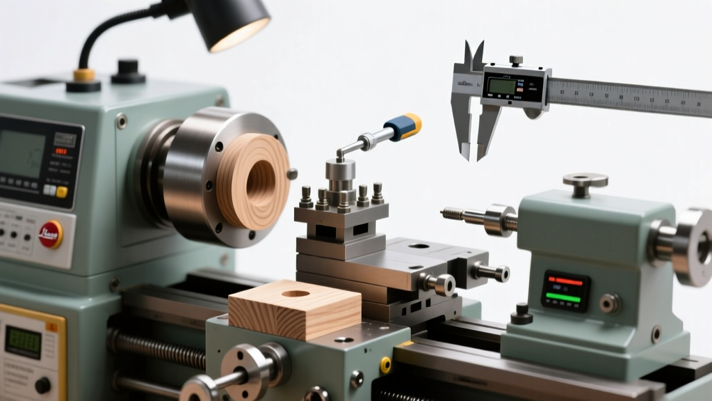
Types of CNC Milling Machines with 1200×600mm Work Envelope
A CNC milling machine with a 1200×600mm work area is engineered to handle large-scale machining tasks with high precision. These machines utilize computer numerical control (CNC) systems to automate cutting operations, enabling consistent and repeatable results across complex geometries. With a generous work envelope, they are ideal for manufacturing large components in industries such as aerospace, automotive, mold-making, and industrial equipment.
These machines typically come equipped with advanced CNC controllers—ranging from basic manual data input (MDI) panels to full graphical user interfaces (GUIs)—that allow operators to program toolpaths, set parameters, and monitor machining processes in real time. The classification of CNC milling machines is primarily based on the orientation of the spindle relative to the machine bed: vertical, horizontal, and universal (multi-axis) configurations. Each type offers distinct advantages depending on the application, material, and required precision.
Vertical CNC Milling Machines
Features a vertically oriented spindle where the cutting tool moves perpendicular to the workpiece surface.
Advantages
- Excellent for precision surface finishing and flat milling
- Ideal for drilling, slotting, and contouring operations
- Widely used for engraving and detailed 2.5D machining
- Easier tool visibility and setup for operators
- Cost-effective for most general-purpose applications
Limitations
- Limited access to deep cavities or side features
- Less efficient for heavy material removal on large faces
- Chip evacuation can be challenging in deep pockets
Best for: Sheet metal processing, mold plates, signage, prototyping, and precision part fabrication on 1200×600mm stock
Horizontal CNC Milling Machines
Equipped with a horizontally mounted spindle, allowing the cutter to rotate parallel to the worktable.
Advantages
- Superior for heavy-duty material removal and high-volume production
- Excellent chip evacuation due to gravity-assisted flow
- Efficient for machining grooves, slots, and complex internal features
- Can use multiple cutters via arbors for simultaneous operations
- Better tool life due to even load distribution
Limitations
- Higher initial investment and larger footprint
- More complex setup and programming requirements
- Less intuitive for beginners compared to vertical mills
Best for: Gear housings, engine blocks, large brackets, and high-efficiency batch production on wide 1200mm workpieces
Universal (Multi-Axis) CNC Milling Machines
Combines both vertical and horizontal milling capabilities, often featuring a rotatable spindle head or a 4th/5th axis rotary table for enhanced flexibility.
Advantages
- Full 3D contouring and complex geometry machining
- Reduced need for multiple setups by enabling multi-sided machining
- High versatility for aerospace, medical, and custom tooling applications
- Optimized workflow for intricate parts requiring angular cuts
- Supports advanced CAM software integration for dynamic toolpaths
Limitations
- Significantly higher cost than standard vertical or horizontal mills
- Requires skilled operators and advanced programming knowledge
- Longer setup times and maintenance complexity
Best for: Complex aerospace components, turbine blades, custom fixtures, and high-precision tooling on large 1200×600mm platforms
| Milling Type | Spindle Orientation | Work Envelope (Typical) | Primary Applications | Automation Compatibility |
|---|---|---|---|---|
| Vertical CNC Mill | Perpendicular to bed | 1200×600×300 mm | Surface milling, engraving, drilling | High (with tool changers) |
| Horizontal CNC Mill | Parallel to bed | 1200×600×400 mm | Heavy cutting, slotting, batch production | Very High (pallet changers) |
| Universal CNC Mill | Adjustable (V/H + rotation) | 1200×600×350 mm + rotary axes | Complex 3D parts, multi-face machining | Advanced (robotic integration) |
Expert Tip: For optimal utilization of a 1200×600mm CNC mill, consider integrating a tool presetting system and automated workholding (like hydraulic clamps or vacuum tables) to reduce cycle times and improve repeatability, especially in production environments.
When selecting a CNC milling machine with a 1200×600mm bed size, it's crucial to evaluate your production needs: vertical mills offer simplicity and precision for surface work, horizontal mills deliver power and efficiency for volume machining, while universal mills provide unmatched flexibility for complex, multi-faceted components. The right choice depends on part geometry, material type, production volume, and available operator expertise.
Industrial Applications of CNC Milling 1200×600 mm: Precision at Scale
The CNC milling machine with a 1200×600 mm work envelope represents a powerful intersection of large-scale capability and micron-level precision. Its expansive working area enables the processing of oversized or complex components, while computer numerical control ensures repeatability, accuracy, and consistency across production runs. This makes it indispensable across industries where both size and precision are critical. From aerospace giants to medical device innovators, the 1200×600 mm CNC mill supports the fabrication of high-performance parts that demand tight tolerances, intricate geometries, and reliable material integrity.
Aerospace Industry: Engineering Flight-Critical Components
Material Challenges
The aerospace sector frequently uses advanced materials such as titanium alloys, Inconel, aluminum-lithium composites, and high-strength stainless steels. These materials offer excellent strength-to-weight ratios and thermal resistance but are notoriously difficult to machine due to their hardness and tendency to generate heat. The 1200×600 mm CNC milling machine is equipped with high-torque spindles and advanced cooling systems to handle these demanding materials effectively.
Precision & Safety Standards
Aircraft components—such as turbine blades, engine mounts, wing spars, and landing gear housings—require tolerances within ±0.005 mm to ensure structural integrity and aerodynamic performance. CNC milling guarantees this level of accuracy, reducing human error and ensuring compliance with AS9100 and other aerospace quality standards. The large bed size also allows for full-scale machining of structural elements without the need for assembly from smaller sections.
Automotive Manufacturing: Driving Innovation in Production
Prototyping and Tooling
In automotive design and manufacturing, the 1200×600 mm CNC mill is extensively used for creating molds, dies, jigs, and fixtures. These tools are essential for stamping, casting, and assembling vehicle components. The machine’s capacity allows for single-piece mold production for large body panels or chassis parts, minimizing seams and improving consistency in mass production.
Engine and Transmission Systems
High-performance engines and transmissions rely on precisely machined parts such as cylinder heads, crankshafts, camshafts, and gearboxes. CNC milling ensures dimensional accuracy and surface finish quality critical for optimal combustion efficiency, reduced friction, and long-term durability. The repeatability of CNC processes also supports just-in-time manufacturing and reduces scrap rates in high-volume production environments.
Electronics Production: Enabling Miniaturization and Integration
PCB Prototyping and Enclosures
While electronics involve small components, many enclosures, heat sinks, and chassis for industrial electronics, servers, and communication devices require precise milling of aluminum or composite materials. The large bed of the CNC mill allows for batch processing of multiple PCB panels or full-sized server racks, enhancing throughput. It also supports rapid prototyping of custom electronic housings with exact cutouts for connectors, vents, and mounting hardware.
Micro-Machining Capabilities
Despite its large size, modern 1200×600 mm CNC mills can be fitted with micro-tooling and high-speed spindles to perform fine-detail work. This dual capability enables manufacturers to produce both large structural frames and tiny internal features—such as RF shielding slots or sensor mounts—on the same machine, streamlining production workflows and reducing equipment footprint.
Medical Devices: Precision for Patient Safety
Surgical Instruments and Implants
The medical field demands absolute precision and biocompatibility. CNC milling is used to fabricate surgical tools like forceps, bone drills, and clamps, as well as patient-specific implants such as cranial plates, hip joints, and dental crowns. Materials like medical-grade titanium (Ti-6Al-4V), cobalt-chrome, and PEEK polymer are machined to exact anatomical specifications derived from CT or MRI scans.
Regulatory Compliance
Medical devices must meet strict regulatory standards (e.g., ISO 13485, FDA 21 CFR Part 820). CNC milling provides full traceability through digital programming, tool path documentation, and automated quality checks. The ability to maintain sterile surface finishes and avoid material stress during machining further enhances the suitability of CNC for life-critical applications.
Industrial Equipment Manufacturing: Building the Machines That Build
Heavy-Duty Component Fabrication
Large-scale CNC milling is vital for producing core components of industrial machinery, including gearboxes, pump housings, conveyor frames, and robotic arms. These parts often require deep cavities, complex internal channels, or multi-axis contours that only CNC technology can achieve efficiently. The 1200×600 mm platform accommodates oversized castings or forgings, allowing complete machining in a single setup to minimize alignment errors.
Mass Production Efficiency
With automated tool changers, pallet systems, and integrated probing, CNC mills enable lights-out manufacturing for high-volume industrial parts. Programs can run unattended for hours, significantly reducing labor costs and increasing output. The consistency of CNC machining also reduces wear on downstream equipment by ensuring perfect fit and alignment of machined components.
| Industry | Common Materials | Typical Components | Tolerance Range |
|---|---|---|---|
| Aerospace | Titanium, Inconel, Aluminum Alloys | Wing spars, engine casings, landing gear | ±0.005 – ±0.01 mm |
| Automotive | Cast Iron, Steel, Aluminum | Cylinder heads, transmission cases, molds | ±0.01 – ±0.02 mm |
| Electronics | Aluminum, Brass, Plastics | Enclosures, heat sinks, PCB panels | ±0.02 – ±0.05 mm |
| Medical | Ti-6Al-4V, Cobalt-Chrome, PEEK | Implants, surgical tools, prosthetics | ±0.005 – ±0.01 mm |
| Industrial Equipment | Carbon Steel, Stainless Steel, Cast Iron | Gears, shafts, housings, frames | ±0.01 – ±0.03 mm |
Why the 1200×600 mm CNC Mill Stands Out
Important: To fully leverage the capabilities of a 1200×600 mm CNC milling machine, proper fixturing, tool selection, and programming are essential. Poor setup can lead to vibration, tool breakage, or dimensional inaccuracies. Always follow manufacturer guidelines for maintenance, coolant management, and spindle load limits. Investing in skilled operators and regular calibration ensures long-term reliability and optimal return on investment.
Product Specifications and Features of CNC Milling Machine 1200×600mm
The CNC milling machine with a 1200×600mm worktable is a versatile and powerful tool designed for precision machining in industrial, prototyping, and manufacturing environments. Engineered for accuracy, durability, and efficiency, this machine supports a wide range of materials—from aluminum and steel to plastics and composites. Below is a comprehensive overview of its technical specifications, operational guidelines, and maintenance best practices to ensure optimal performance and longevity.
Technical Specifications
Understanding the core technical parameters of the CNC milling machine is essential for selecting the right applications and maximizing productivity. These specifications define the machine's capabilities and limitations.
Worktable Dimensions & Load Capacity
- Worktable Area: 1200 mm × 600 mm – provides a large surface for securing multiple or oversized workpieces, ideal for batch production or complex machining tasks.
- Max Load Capacity: Up to 300 kg – ensures the table can support heavy-duty materials such as cast iron, thick aluminum blocks, or steel plates without deformation.
- Table Features: Precision-ground surface with T-slots for secure clamping using vises, fixtures, or custom jigs.
Note: Even weight distribution is crucial to maintain accuracy and prevent table warping over time.
Spindle & Motor Performance
- Spindle Speed: Up to 2400 RPM – adjustable via variable frequency drive (VFD), allowing customization based on material type and tooling requirements.
- Motor Power: 5.5 kW (approximately 7.5 HP) – delivers robust torque for deep cuts and hard materials like stainless steel or titanium.
- Spindle Taper: Typically ISO 30 or BT30, compatible with a wide range of tool holders.
Tip: Lower speeds (800–1500 RPM) are ideal for steel; higher speeds (1800–2400 RPM) suit aluminum and plastics.
Axis Travel & Precision
- Axis Movement: X, Y, and Z axes each offer 600 mm of travel, enabling full utilization of the worktable area and deep 3D profiling.
- Positioning Accuracy: ±0.01 mm – ensures tight tolerances for precision engineering applications.
- Repeatability: ±0.005 mm – critical for consistent results in repeated production runs.
Technical Insight: Ball screws and linear guides ensure smooth, backlash-free motion across all axes.
Cutting Tools & Compatibility
- Common Tool Types: End mills (square, corner radius), ball nose cutters (for 3D contours), face mills (for surface finishing), and slot drills.
- Tool Holding: Uses standard ER collets or hydraulic chucks for secure grip and minimal runout.
- Tool Diameter Range: Typically supports tools from 3 mm to 20 mm, depending on spindle bore size.
Best Practice: Always balance high-speed tools and check for runout before operation.
| Parameter | Specification | Application Benefit |
|---|---|---|
| Worktable Size | 1200 × 600 mm | Large workpiece handling and multi-part setups |
| Spindle Speed | Up to 2400 RPM (variable) | Adaptable to various materials and cutting strategies |
| Motor Power | 5.5 kW | Suitable for heavy-duty milling and hard metals |
| Axis Travel (X/Y/Z) | 600 mm each | Full 3D machining capability within worktable limits |
| Max Workpiece Load | 300 kg | Supports industrial-grade materials and tooling |
Installation and Operation Guide
Proper setup and use are critical to achieving precision results and ensuring operator safety. Follow these steps for reliable and efficient CNC milling operations.
Installation Steps
- Foundation Preparation: Install the machine on a level, vibration-resistant concrete floor. Use anti-vibration pads or mounts to minimize external disturbances.
- Power Requirements: Ensure a stable 3-phase power supply (typically 380V/50Hz) with proper grounding. Voltage fluctuations can damage control systems.
- Control System Setup: Connect the CNC controller, motor drivers, and spindle inverter according to the manufacturer’s wiring diagram. Verify all connections are secure.
- Initial Calibration: Perform homing cycles and axis calibration to establish machine zero and ensure accurate positioning.
Operational Workflow
- Tool Selection: Choose the appropriate cutter based on the operation—end mills for profiling, ball nose for 3D surfaces, and face mills for rapid material removal.
- Workpiece Fixturing: Secure the material using clamps, vises, or vacuum tables. Ensure the workpiece is flat and aligned with the machine axes.
- Software Programming: Design the part in CAD software (e.g., Fusion 360, SolidWorks), then generate toolpaths using CAM software. Simulate the program to detect collisions or errors.
- Program Transfer: Load the G-code into the CNC controller via USB, Ethernet, or direct connection. Set work offsets (G54–G59) and verify tool lengths.
- Execution: Start the machine in single-block mode for the first run, monitoring tool engagement and cutting conditions. Switch to automatic mode once confirmed.
Pro Tip: Always perform a dry run without a tool or workpiece to validate the program path and avoid costly collisions. Use tool presetters for accurate length measurement and reduce setup time.
Maintenance and Repair Best Practices
Regular maintenance extends the machine’s lifespan, maintains accuracy, and prevents unexpected downtime. A proactive maintenance schedule is essential for industrial environments.
Daily & Weekly Maintenance
- Cleaning: Remove metal chips, coolant residue, and dust from the worktable, ways, and spindle housing after each use.
- Tool Inspection: Check cutting tools for wear, chipping, or breakage. Replace worn tools promptly to avoid poor surface finish or tool failure.
- Lubrication: Apply manufacturer-recommended lubricants to linear rails, ball screws, and lead screws on a scheduled basis (daily or weekly).
Safety Note: Always power off the machine before performing maintenance tasks.
Cooling & System Checks
- Cooling System: Inspect coolant levels and flow rate regularly. Clean filters and nozzles to prevent clogging and ensure proper chip evacuation.
- Air Filters: Clean or replace air intake filters for the electrical cabinet to prevent overheating of CNC components.
- Belt Tension: Check spindle drive belts for proper tension and signs of wear. Loose belts reduce spindle performance and cause slippage.
- Software Updates: Keep the CNC control software up to date for improved functionality and bug fixes.
Preventive Tip: Keep a maintenance log to track service intervals and identify recurring issues early.
Additional Considerations
- Noise & Safety: Operate in a well-ventilated area with hearing protection. Install safety enclosures or curtains to protect operators from flying chips.
- Environmental Conditions: Maintain ambient temperature between 15–30°C and humidity below 75% to protect electronics.
- Training: Ensure operators are trained in G-code basics, emergency stops, and crash recovery procedures.
- Upgrade Options: Consider adding automatic tool changers (ATC), probing systems, or fourth-axis rotary tables for increased versatility.
- Warranty & Support: Register the machine with the manufacturer and keep service contracts active for technical support and spare parts access.
Professional Recommendation: For optimal results, pair this CNC milling machine with high-quality cutting tools and premium coolants. Invest in operator training and preventive maintenance to maximize uptime and precision. Regular calibration and alignment checks will ensure long-term accuracy and reliability in demanding production environments.
Quality and Safety Considerations for CNC Milling 1200 x 600mm Machines
Operating a large-format CNC milling machine with a 1200 x 600mm work envelope requires strict adherence to quality control and safety protocols. These industrial machines offer high precision and efficiency but also pose significant risks if not handled properly. This guide outlines essential best practices for material handling, tool selection, and operational safety to ensure optimal performance, component longevity, and workplace safety when working with large-scale milling systems.
Safety Alert: Large CNC milling machines generate high forces and produce fast-moving cutters and flying debris. Always follow manufacturer guidelines and workplace safety regulations. Never bypass safety interlocks or operate the machine without proper training and protective equipment.
Quality Control in CNC Milling Operations
- Accurate Material Identification: Correctly identifying the workpiece material is fundamental to successful CNC milling. Different materials—such as aluminum, steel, brass, plastics, or composites—require specific cutting speeds (SFM or m/min), feed rates (mm/tooth), and depth of cut. Refer to authoritative CNC machining charts or CAM software databases to determine optimal parameters. For example, aluminum typically allows higher speeds than hardened steel, and improper settings can lead to tool chipping, work hardening, or poor surface finish.
- Precision Workholding: On a 1200 x 600mm table, consistent clamping across the entire surface is crucial. Use appropriate vises, T-slots, vacuum fixtures, or modular fixturing systems to secure the workpiece firmly and prevent vibration or shifting during cutting. Uneven clamping pressure can result in dimensional inaccuracies or tool breakage.
- Tool Selection and Application: Choosing the correct cutting tool directly impacts machining efficiency and part quality. Consider the following:
- End Mills: Ideal for slotting, profiling, and facing. Choose flute count based on material—2-3 flutes for aluminum (chip clearance), 4+ flutes for steel (finishing).
- Ball Nose Cutters: Used for 3D contouring and sculpted surfaces, especially in mold and die work.
- Face Mills: Best for rapid material removal and achieving flat surface finishes on large areas.
- Corner Radius Mills: Provide increased tool strength and better surface finish on sharp edges.
- Toolpath Optimization: Utilize CAM software to generate efficient toolpaths that minimize tool load variations and avoid sudden direction changes. For large tables, consider step-over strategies, adaptive clearing, and high-efficiency milling (HEM) techniques to extend tool life and reduce cycle times.
- Surface Finish and Tolerance Management: Monitor surface roughness and dimensional accuracy using calibrated measuring tools (micrometers, calipers, CMMs). Adjust spindle speed, feed rate, and coolant flow as needed to meet specified tolerances (e.g., ±0.02mm) and surface finishes (e.g., Ra 1.6 µm).
Safety Considerations for CNC Milling Operations
- Personal Protective Equipment (PPE): All personnel in the machining area must wear:
- ANSI Z87.1-approved safety glasses or face shields to protect against flying chips and coolant mist
- Hearing protection (earplugs or earmuffs), especially during prolonged milling cycles
- Cut-resistant gloves when handling sharp tools or raw materials (but never while operating the machine)
- Steel-toed boots to protect feet from falling objects
- Emergency Stop Systems: Familiarize yourself with the location and function of all emergency stop (E-stop) buttons on the CNC machine. These are typically bright red and mushroom-shaped, placed at multiple access points. Pressing an E-stop immediately cuts power to the spindle and axes, halting all motion. Test E-stop functionality during routine maintenance and ensure they are never obstructed.
- Machine Guarding and Interlocks: Safety guards must remain closed during operation. These enclosures prevent access to rotating spindles, moving axes, and chip ejection zones. Interlock systems automatically pause the machine if a door is opened. Never disable or bypass safety interlocks—even for quick adjustments—as this dramatically increases the risk of serious injury.
- Work Area Organization: Maintain a clean, clutter-free workspace around the 1200 x 600mm machine:
- Remove tools, coolant containers, and unused materials from the floor and control panel area
- Use chip conveyors or vacuum systems to manage metal shavings, which can be hot and sharp
- Ensure proper lighting and clear walkways to prevent trips and falls
- Post clear signage indicating hazardous zones during machine operation
- Operator Focus and Distraction Prevention: Once the CNC cycle begins, the operator must remain attentive. Avoid distractions such as mobile phones or conversations. Monitor the machine for unusual vibrations, noises, or tool wear. Never reach into the work envelope while the spindle is rotating or axes are active.
- Coolant and Chip Management: Use appropriate coolant delivery to reduce heat and improve tool life. Ensure mist collectors are functioning to prevent inhalation of airborne particles. Regularly clean chip build-up, which can interfere with linear guides and ball screws.
| Safety/Quality Factor | Best Practices | Risks of Non-Compliance | Recommended Tools/Equipment |
|---|---|---|---|
| Material Identification | Verify material grade; consult cutting data charts | Tool breakage, poor surface finish, workpiece damage | Material test reports, CAM software, speed/feet calculators |
| Tool Selection | Match tool geometry and coating to material and operation | Reduced tool life, chatter, dimensional inaccuracy | End mills, collet checkers, runout testers |
| PPE Usage | Wear safety glasses, hearing protection, proper footwear | Eye injuries, hearing loss, lacerations | Safety glasses, ear protection, steel-toed boots |
| Machine Guarding | Keep guards closed; never bypass interlocks | Crush injuries, entanglement, amputation risk | Interlocked doors, light curtains, E-stop buttons |
| Work Area Cleanliness | Clear chips and obstacles; organize tools | Trips, slips, machine interference | Chip vacuums, brooms, storage trays |
Expert Tip: Conduct a pre-machining checklist before each job: verify tooling setup, confirm workpiece alignment, double-check G-code for errors, and ensure all safety systems are functional. This simple routine can prevent costly mistakes and enhance both safety and part quality.
Maintenance and Continuous Improvement
- Schedule regular maintenance for ball screws, linear guides, and spindle bearings to maintain accuracy on large-format machines
- Keep a log of tool life, material types, and process outcomes to refine future operations
- Provide ongoing training for operators on new tooling, software updates, and safety procedures
- Review near-misses or tool failures to improve processes and prevent recurrence
- Ensure proper ventilation and air filtration in the machining area, especially when cutting toxic materials like composites or coated metals
Operating a 1200 x 600mm CNC milling machine demands a disciplined approach to both quality and safety. By integrating proper material handling, precise tooling strategies, and rigorous safety protocols, manufacturers can achieve high-precision results while protecting personnel and equipment. Always prioritize safety over speed, and remember that a well-maintained, carefully operated machine delivers consistent, reliable performance over its lifespan.
Frequently Asked Questions About CNC Milling
Q1. What is the benefit of using CNC milling over traditional milling methods?CNC (Computer Numerical Control) milling offers several significant advantages over traditional manual milling, making it the preferred choice in modern manufacturing environments. The primary benefits include:
- Enhanced Precision: CNC machines operate with micron-level accuracy, consistently producing parts that meet exact design specifications without human error.
- Improved Consistency: Once a program is set, the machine can replicate identical components thousands of times with no variation, ensuring uniform quality across large production runs.
- Greater Complexity: Multi-axis CNC mills can create intricate geometries—such as undercuts, contours, and internal features—that would be extremely difficult or impossible to achieve manually.
- Increased Efficiency: Automation allows for continuous operation, including unattended machining during off-hours, significantly boosting productivity and reducing labor costs.
- Reduced Operator Fatigue: Unlike manual milling, which requires constant attention and physical effort, CNC systems minimize human involvement, lowering the risk of mistakes due to fatigue.
These capabilities make CNC milling ideal for industries where tight tolerances, repeatability, and complex designs are critical.
Q2. How does CNC milling contribute to material waste minimization?CNC milling plays a crucial role in sustainable manufacturing by significantly reducing material waste through advanced digital optimization. Here’s how:
- Precise Toolpath Programming: CAM (Computer-Aided Manufacturing) software calculates exact cutting paths that follow the 3D model geometry, removing only the necessary material and avoiding overcutting.
- Simulation and Verification: Before any physical cutting begins, the entire machining process can be simulated to detect errors or inefficiencies, preventing costly material loss from incorrect operations.
- Optimized Nesting: Multiple parts can be arranged efficiently on a single workpiece (especially in sheet or block materials), maximizing material usage and minimizing scrap.
- High Repeatability: Since each part is produced identically, there are fewer rejected pieces due to dimensional inaccuracies, further reducing waste.
- Integration with Lean Manufacturing: CNC systems support just-in-time production and on-demand fabrication, reducing the need for excess inventory and associated material overproduction.
By combining software intelligence with mechanical precision, CNC milling ensures that raw materials—especially expensive metals like titanium or aerospace alloys—are used as efficiently as possible.
Q3. What forms the basis of the CNC milling machine's working principle?The working principle of a CNC milling machine revolves around the integration of computerized control systems with mechanical machining processes. At its core, the system operates in the following way:
- Digital Design Input: A 3D model created in CAD (Computer-Aided Design) software is converted into a set of machine-readable instructions using CAM software. These instructions are written in G-code, the standard language for CNC machines.
- Automated Tool Movement: The CNC controller interprets the G-code and precisely directs the movement of the spindle and cutting tools along multiple axes (typically 3 to 5 axes), shaping the workpiece according to the design.
- Material Removal Process: Rotating cutting tools engage with the workpiece, systematically removing material through processes like face milling, end milling, drilling, or contouring.
- Feedback and Control Systems: Modern CNC machines often include sensors and closed-loop systems that monitor position, speed, and load, adjusting in real time to maintain accuracy and prevent errors.
- Clamping and Fixturing: The workpiece is securely held in place using vises, clamps, or custom fixtures to ensure stability during high-speed operations.
This synergy between digital programming and mechanical execution enables CNC milling to produce highly accurate, repeatable, and complex components with minimal human intervention.
Q4. Which industries benefit the most from CNC milling?CNC milling has become an indispensable technology across numerous high-precision industries. The following sectors rely heavily on CNC machining due to their demand for accuracy, reliability, and performance:
| Industry | Key Applications | Materials Commonly Used |
|---|---|---|
| Aerospace | Turbine blades, engine mounts, landing gear components, structural airframe parts | Titanium, aluminum alloys, Inconel, composites |
| Automotive | Engine blocks, transmission housings, custom prototypes, suspension components | Aluminum, steel, magnesium, plastics |
| Medical | Implants (hip/knee joints), surgical instruments, prosthetics, diagnostic equipment | Stainless steel, titanium, PEEK, cobalt-chrome alloys |
| Electronics | Heat sinks, enclosures, connectors, semiconductor tooling | Aluminum, copper, plastics, ceramics |
| Defense & Energy | Military hardware, missile components, oil/gas valves, nuclear reactor parts | High-strength steels, exotic alloys, hardened materials |
These industries benefit not only from the precision and repeatability of CNC milling but also from its ability to scale from rapid prototyping to full-scale production, making it a cornerstone of advanced manufacturing.
Q5. How frequent should the CNC milling machine undergo maintenance?Regular and proactive maintenance is essential to ensure the longevity, accuracy, and safe operation of CNC milling machines. The frequency and type of maintenance depend on usage intensity, but a structured schedule typically includes:
- Daily Maintenance: Clean the work area, remove chips and coolant residue, check lubrication levels, inspect for unusual noises or vibrations, and verify emergency stop functionality.
- Weekly Maintenance: Inspect and clean ball screws, linear guides, and ways; check for leaks in hydraulic or coolant systems; test spindle runout and tool holder condition.
- Monthly Maintenance: Calibrate axes and encoders, inspect electrical connections, verify coolant concentration and pH levels, and examine drive belts or gears for wear.
- Quarterly/Annual Maintenance: Perform full system diagnostics, replace filters and worn components, re-lubricate all moving parts, and conduct precision alignment checks (e.g., squareness, parallelism).
- Usage-Based Servicing: Follow manufacturer recommendations based on operating hours (e.g., 1,000–5,000 hours) for major services like spindle rebuilds or controller updates.
Implementing a preventive maintenance program not only extends machine life but also reduces unexpected downtime, maintains dimensional accuracy, and ensures consistent product quality. Many modern CNC systems come with built-in diagnostic tools and maintenance alerts to assist operators in scheduling timely servicing.