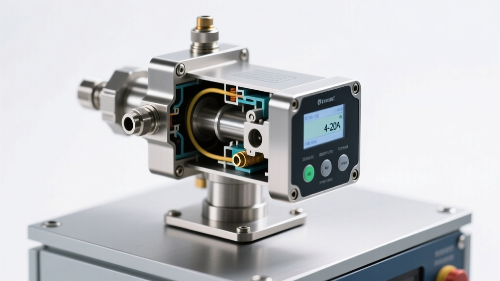
Types of 4-20mA Liquid Flow Sensors
A 4-20mA liquid flow sensor is an industrial instrument that measures the rate or volume of liquid flow and transmits this data via a standardized analog current signal (4 to 20 milliamps). This output is widely used in process control systems due to its noise resistance and compatibility with PLCs and SCADA systems.
These sensors come in several types, each based on different operating principles and suited for specific applications. Choosing the right type depends on factors like fluid properties, required accuracy, environmental conditions, and system integration needs. Below is a detailed overview of the most common types:
Turbine Flow Sensors
These sensors use a rotating impeller or rotor placed directly in the fluid stream. As liquid flows through the sensor, it causes the rotor to spin at a speed proportional to the flow velocity.
Advantages
- High accuracy for clean liquids
- Fast response time
- Linear output signal
- Ideal for low-viscosity fluids
Limitations
- Sensitive to debris and particulates
- Wear over time due to moving parts
- Not suitable for viscous or abrasive fluids
Best for: Water treatment, fuel measurement, chemical dosing, and clean liquid applications
Ultrasonic Flow Meters
These non-invasive meters use ultrasonic waves transmitted through the pipe wall to measure flow velocity. They calculate flow rate by comparing the time it takes for sound waves to travel with and against the flow (time-of-flight method).
Advantages
- No contact with the fluid (clamp-on models)
- No pressure drop
- Works with various pipe sizes and materials
- Bi-directional flow measurement
Limitations
- Requires homogeneous, particle-free fluid
- Accuracy affected by air bubbles or scaling
- Higher initial cost
Best for: Water distribution, HVAC systems, wastewater monitoring, and retrofit installations
Magnetic Flow Sensors (Magmeters)
These sensors operate on Faraday’s Law of Electromagnetic Induction. When a conductive liquid passes through a magnetic field, it generates a voltage proportional to flow velocity. Electrodes detect this voltage and convert it into a 4-20mA signal.
Advantages
- No moving parts – highly reliable
- Excellent for dirty, corrosive, or abrasive liquids
- Unaffected by changes in temperature, density, or viscosity
- Full-bore design minimizes clogging
Limitations
- Only works with conductive fluids (minimum conductivity required)
- Cannot measure hydrocarbons or deionized water
- Requires full pipe for accurate readings
Best for: Wastewater, slurries, acids, caustics, food & beverage processing
Vortex Flow Sensors
These sensors use a bluff body placed in the flow stream to create alternating vortices. The frequency of these vortices is directly proportional to the flow rate and is detected using piezoelectric or capacitive sensors.
Advantages
- Durable with no moving parts in contact with fluid
- Good for high-temperature and high-pressure applications
- Stable long-term performance
- Measures mass flow when combined with temperature/pressure inputs
Limitations
- Requires minimum flow velocity to generate vortices
- Not ideal for low-flow or viscous fluids
- Sensitive to vibrations and piping disturbances
Best for: Steam, hot water, gases, and industrial process lines with stable flow profiles
Positive Displacement (PD) Flow Meters
These meters divide the liquid into fixed, metered volumes using internal chambers (such as gears, pistons, or rotors). Each rotation corresponds to a known volume, which is converted into a 4-20mA signal.
Advantages
- Extremely high accuracy, even at low flow rates
- Direct volumetric measurement
- Unaffected by flow profile or turbulence
- Effective with fluids containing entrained air or bubbles
Limitations
- Moving parts subject to wear and jamming
- Creates pressure drop across the meter
- Limited to clean or filtered fluids
Best for: Custody transfer, chemical injection, oil & gas metering, and batching applications
| Sensor Type | Accuracy | Fluid Compatibility | Key Strengths | Typical Applications |
|---|---|---|---|---|
| Turbine | ±0.5% of reading | Clean, low-viscosity liquids | High precision, fast response | Fuel, solvents, purified water |
| Ultrasonic | ±1% of reading | Homogeneous liquids, full pipes | Non-invasive, no pressure loss | HVAC, water supply, retrofits |
| Magnetic | ±0.2–0.5% | Conductive liquids only | No moving parts, handles slurry | Wastewater, chemicals, food |
| Vortex | ±1% of rate | Liquids, steam, gases | Durable, handles high temps | Process heating, steam lines |
| Positive Displacement | ±0.1–0.2% | Viscous, aerated liquids | High accuracy, low flow capable | Custody transfer, dosing |
Expert Tip: Always ensure proper installation—especially upstream and downstream straight pipe requirements—to avoid turbulence and inaccurate readings. For 4-20mA systems, verify loop power supply and grounding to prevent signal noise and calibration drift.
Industry Applications of 4-20mA Liquid Flow Sensors
4-20mA liquid flow sensors are essential components in modern industrial automation and process control systems. Their ability to deliver reliable, noise-resistant analog signals makes them ideal for monitoring and managing fluid dynamics across a wide range of critical applications. Among the most vital uses is in fixed fuel tank transfer systems, where precise flow measurement ensures operational safety, efficiency, and system redundancy.
Role in Fixed Fuel Tank Transfer Systems
In fixed fuel tank transfer systems, the 4 to 20 mA liquid flow sensor plays a pivotal role in maintaining optimal gas and fuel ratios during transfer operations. By continuously monitoring the flow rate of liquids—such as diesel, gasoline, or biofuels—the sensor provides real-time feedback to control systems, enabling automatic regulation of pumping rates and valve actuation.
This capability is crucial for preventing over-reliance on a single fuel source, allowing seamless switching between multiple tanks based on availability and demand. During tank refilling operations, the sensor ensures that inflow rates remain within safe limits, avoiding overflow, pressure buildup, or cavitation that could damage equipment or compromise safety.
Moreover, the 4-20mA signal output is highly resistant to electrical interference, making it suitable for long cable runs commonly found in large-scale fuel storage facilities. This reliability ensures consistent performance even in electrically noisy environments, such as near motors, generators, or high-voltage equipment.
Fuel Equilibrium Management
One of the key benefits of integrating a 4-20mA flow sensor into a fuel tank system is its ability to maintain fuel equilibrium across interconnected tanks. By detecting imbalances in flow rates, the sensor enables control systems to adjust transfer pumps and balance valves automatically, ensuring uniform distribution and preventing overfilling or dry-running conditions.
This is particularly important in backup power systems, marine vessels, and remote energy installations where consistent fuel delivery is critical for uninterrupted operation.
Safety and Leak Detection
These sensors also contribute significantly to system safety. Unexpected changes in flow—such as sudden drops or zero-flow conditions—can indicate leaks, blockages, or pump failures. When integrated with SCADA (Supervisory Control and Data Acquisition) systems, the 4-20mA signal allows for immediate alarm triggering and automated shutdown procedures, minimizing environmental risks and financial losses.
Broader Industrial Applications
While fuel transfer systems represent a key application, 4-20mA liquid flow sensors are widely used across numerous industries due to their durability, accuracy, and compatibility with industrial control systems.
| Industry | Application | Benefit of 4-20mA Sensor |
|---|---|---|
| Energy | Fuel tank transfer, generator feeding | Prevents overfilling, ensures fuel redundancy |
| Manufacturing | Coolant circulation, hydraulic systems | Protects machinery from dry-run conditions |
| Marine | Bunkering, ballast, and fuel balancing | Enables real-time monitoring across vessel tanks |
| Agriculture | Irrigation, fertilizer injection | Optimizes resource use and reduces waste |
Important: Proper installation, calibration, and grounding are essential for accurate 4-20mA flow sensor operation. Always follow manufacturer guidelines and use shielded cables in electrically noisy environments. Regular maintenance and verification against known flow standards help ensure long-term reliability and measurement integrity.
How to Choose a 4-20mA Liquid Flow Sensor
Selecting the right 4-20mA liquid flow sensor is crucial for accurate process monitoring, system efficiency, and long-term reliability in industrial, commercial, and automation applications. These sensors convert flow rate into a standardized analog signal (4-20mA), making them ideal for integration with PLCs, SCADA systems, and control panels. However, choosing the best sensor requires careful evaluation of several technical and environmental factors to ensure optimal performance and safety.
Fluid Type and Compatibility
The nature of the liquid being measured is one of the most critical considerations. Different fluids have unique chemical and physical properties that directly impact sensor selection, including viscosity, conductivity, pH level, and potential for abrasiveness.
- Water and mild liquids: Standard sensors with PVC, PPS, or stainless steel wetted parts are typically sufficient
- Corrosive fluids (acids, alkalis): Require chemically resistant materials like PTFE, PVDF, or Hastelloy
- Viscous or slurry-based fluids: May need specialized designs such as paddlewheel or electromagnetic sensors with larger flow paths
- Conductive vs. non-conductive: Electromagnetic sensors require conductive fluids, while turbine or ultrasonic types work with both
Key consideration: Always verify material compatibility charts to prevent corrosion, swelling, or sensor failure.
Environmental and Operating Conditions
The installation environment plays a major role in sensor durability and performance. Extreme temperatures, pressure fluctuations, vibration, and exposure to hazardous substances can degrade sensor components over time.
- Sensors for outdoor or high-humidity areas should have at least IP65 or NEMA 4X ratings
- High-temperature applications (>80°C) require sensors with heat-resistant seals and electronics
- Explosive or flammable environments may necessitate intrinsically safe or explosion-proof certified models
- High-vibration areas benefit from solid-state designs (e.g., ultrasonic) over mechanical moving parts
Pro tip: Consider ambient temperature effects on signal stability and calibration drift.
Accuracy, Flow Range, and Signal Output
The sensor must match the required flow measurement range and precision for your application. The 4-20mA output provides a linear signal (4mA = zero flow, 20mA = full scale), but performance depends on proper calibration and range selection.
- Ensure the sensor’s minimum and maximum flow rates align with your process needs
- Typical accuracy ranges from ±0.5% to ±2% of reading—higher precision increases cost
- Low-flow applications may require specialized sensors with enhanced sensitivity
- Verify loop power requirements (typically 12–24V DC) and cable length limitations
Critical factor: Mismatched range can lead to signal saturation or poor resolution at low flows.
Regulatory and Safety Standards
Compliance with industry and safety regulations ensures reliable, legal, and safe operation—especially in food, pharmaceutical, and chemical processing.
- OSHA and OSHA-aligned standards: Ensure worker safety in high-pressure or hazardous environments
- CE, ATEX, or IECEx: Required for use in potentially explosive atmospheres
- 3-A Sanitary Standards: Essential for food and beverage applications
- UL or CSA certification: Validates electrical safety and performance in North America
Smart choice: Always verify certifications before deployment in regulated industries.
Maintenance and Durability
Long-term reliability and ease of maintenance significantly impact operational costs and system uptime. Sensors with moving parts generally require more frequent servicing than solid-state alternatives.
- Turbine and paddlewheel sensors may need periodic cleaning or bearing replacement
- Ultrasonic and electromagnetic sensors offer minimal maintenance due to no moving parts
- Self-cleaning or flush-mounted designs reduce clogging in dirty or viscous media
- Look for sensors with diagnostic outputs or alarm functions for predictive maintenance
Time-saving tip: Choose sensors with modular or replaceable sensing elements to minimize downtime.
Installation and Integration
Proper installation ensures accurate readings and long service life. Consider piping requirements, orientation, and compatibility with existing control systems.
- Ensure adequate upstream and downstream straight pipe runs to avoid turbulence
- Verify pipe diameter compatibility—some sensors are inline, others are insertion-type
- Check for grounding requirements, especially with electromagnetic sensors
- Ensure compatibility with your control system’s input cards and signal conditioning
Technical note: Improper installation is the leading cause of inaccurate flow readings.
Professional Recommendation: For most general-purpose applications, electromagnetic or ultrasonic 4-20mA flow sensors offer excellent accuracy, durability, and low maintenance. When dealing with conductive liquids in harsh environments, electromagnetic sensors are ideal. For non-conductive fluids or cost-sensitive projects, consider turbine or paddlewheel types with proper filtration. Always consult the manufacturer’s datasheet and consider future scalability when selecting your sensor.
| Application Type | Recommended Sensor Type | Material Compatibility | Typical Accuracy |
|---|---|---|---|
| Water treatment / HVAC | Electromagnetic | Stainless steel, PTFE lining | ±0.5% of reading |
| Chemical dosing | Paddlewheel | PVDF, ceramic shaft | ±1% of reading |
| Food & beverage | Sanitary electromagnetic | 316L SS, EPDM/PTFE seals | ±0.3% of reading |
| Industrial cooling | Ultrasonic (clamp-on) | Non-invasive, no wetted parts | ±1.5% of reading |
Additional Selection Tips
- Signal Stability: Look for sensors with built-in damping or filtering to reduce noise in variable flow conditions
- Zero Calibration: Some sensors allow field calibration to adjust for drift or changing process conditions
- Wetted vs. Non-wetted: Clamp-on ultrasonic sensors avoid direct contact, ideal for retrofits or corrosive fluids
- Lifetime Cost: Consider total cost of ownership—higher initial cost may save on maintenance and downtime
- Vendor Support: Choose manufacturers that provide technical documentation, calibration certificates, and responsive support
Liquid Flow Sensor Specifications and Features: A Complete Guide
Liquid flow sensors are essential components in industrial, commercial, and residential systems where accurate monitoring of fluid movement is critical. These sensors provide real-time data on flow rate, enabling automation, efficiency optimization, and system protection. This guide covers the key specifications, installation procedures, operational principles, and maintenance practices for liquid flow sensors, with a focus on 4-20 mA output models widely used in process control applications.
Important Note: Always verify compatibility between the sensor, fluid medium, and operating environment before installation. Mismatched materials or incorrect calibration can lead to sensor failure, inaccurate readings, or safety hazards.
Technical Specifications and Key Features
Liquid flow sensors, particularly those with 4-20 mA analog output, are designed for seamless integration into control systems. The 4-20 mA signal is industry-standard due to its noise resistance and ability to transmit over long distances without signal degradation.
Power Supply Options
- Loop-powered (2-wire) sensors: These operate using the 4-20 mA current loop itself, drawing power from the connected controller or transmitter. Ideal for remote or low-power applications.
- Externally powered (3 or 4-wire) sensors: Require a separate power source but often offer higher accuracy, additional features (like digital outputs), and better signal stability.
- Battery-powered models: Used in portable or wireless monitoring systems where wired power is unavailable.
Output and Signal Response
The 4 mA signal typically represents the minimum or zero flow condition, while 20 mA corresponds to the maximum flow rate. The output current varies linearly with the flow rate, allowing control systems to interpret real-time flow changes. Advanced sensors include signal damping and filtering to reduce noise from turbulent flow or pump pulsations.
Pressure and Temperature Ratings
Performance under extreme conditions varies significantly based on design and materials:
- Temperature resistance ranges from standard (-10°C to 120°C) to high-temperature models capable of measuring liquids exceeding 200°C, suitable for steam or hot oil systems.
- Pressure ratings vary from standard industrial (up to 1,000 psi) to high-pressure variants rated for 6,000 psi or more, commonly used in hydraulic and oil & gas applications.
- Always consult the sensor’s datasheet for derating curves at elevated temperatures or pulsating flow conditions.
Wetted Materials and Housing Options
The sensor body and internal components must be compatible with the liquid medium to prevent corrosion, contamination, or mechanical failure:
- Stainless steel (304/316): Offers excellent corrosion resistance and durability; ideal for water, chemicals, and food-grade applications.
- Brass: Cost-effective and suitable for water and mild chemicals; may corrode in high-chloride environments.
- Plastics (PVC, PVDF, PPS): Lightweight and chemically inert; used in corrosive environments or where metal contamination must be avoided.
- Aluminum: Lightweight but less corrosion-resistant; typically used in non-corrosive, low-pressure applications.
Material selection should also consider environmental factors such as humidity, UV exposure, and mechanical stress.
| Feature | Standard Range | High-Performance Options | Key Applications |
|---|---|---|---|
| Output Signal | 4-20 mA (2-wire) | 4-20 mA + HART, Modbus, or pulse output | Process control, SCADA systems |
| Temperature Range | -10°C to 120°C | Up to 250°C | Boilers, heat exchangers, chemical processing |
| Pressure Rating | Up to 1,000 psi | Up to 6,000 psi | Hydraulic systems, oil & gas, high-pressure cleaning |
| Housing Materials | Brass, PVC, 304 SS | 316 SS, PVDF, Hastelloy | Pharmaceuticals, seawater, aggressive chemicals |
| Accuracy | ±1% to ±2% of reading | ±0.5% or better | Custody transfer, precision dosing |
Installation Guidelines for Optimal Performance
Proper installation is crucial for accurate and reliable flow measurement. Follow these steps to ensure correct setup:
- Prepare the Installation Site
- Clean the mounting surface and pipe interior to remove debris, rust, or scale that could interfere with flow or damage the sensor.
- Ensure the pipe is free of air pockets or vapor locks, especially in vertical installations.
- Mount the Sensor Correctly
- Install the sensor in the orientation specified by the manufacturer (horizontal, vertical, or angled).
- Use appropriate gaskets or thread sealant (e.g., PTFE tape) to prevent leaks, ensuring no material enters the flow path.
- Tighten fittings evenly using calibrated tools to avoid damaging the sensor housing.
- Electrical Connection
- Follow the wiring diagram provided with the sensor. Typically, 4-20 mA sensors use two wires for signal and power (loop-powered) or separate power and signal lines.
- Use shielded cables in electrically noisy environments and ground the shield at one end to reduce interference.
- Verify polarity and voltage compatibility with the control system.
- System Startup and Verification
- Power on the system and check for proper signal output using a multimeter or HMI interface.
- Verify zero flow reading (4 mA) when the system is closed and full-scale reading (20 mA) at maximum expected flow.
- Perform a basic calibration check if required by the application.
Expert Tip: Install straight pipe runs upstream (10x pipe diameter) and downstream (5x pipe diameter) of the sensor to ensure laminar flow and minimize turbulence, which can cause measurement errors.
How Liquid Flow Sensors Work and How to Use Them
Liquid flow sensors detect and measure the rate of fluid movement through a pipe or conduit. They convert mechanical flow into an electrical signal—most commonly a 4-20 mA current—that is proportional to the flow velocity.
Common sensing technologies include:
- Turbine sensors: Use a rotating impeller; rotation speed correlates to flow rate.
- Electromagnetic (magmeters): Measure voltage induced by conductive fluids moving through a magnetic field.
- Ultrasonic sensors: Use time-of-flight or Doppler shift principles to calculate flow velocity.
- Thermal dispersion: Measure heat loss from a heated element, which varies with flow rate.
The output signal is integrated into control systems such as PLCs, SCADA, or building management systems to enable automated responses—such as adjusting pump speed, triggering alarms, or logging data for analysis. This ensures efficient operation, leak detection, and process optimization.
Maintenance Best Practices
Regular maintenance extends sensor life and ensures measurement accuracy:
- Periodic cleaning: Remove scale, biofilm, or particulate buildup that can obstruct flow or affect sensor elements, especially in water or wastewater systems.
- Visual inspection: Check for leaks, corrosion, or physical damage to the housing and connections.
- Component replacement: Replace worn seals, bearings (in turbine sensors), or damaged cables promptly to prevent system failure.
- Anti-corrosion protection: In aggressive environments (e.g., chemical plants, marine applications), use corrosion-resistant coatings or protective enclosures.
- Calibration verification: Recalibrate sensors annually or as recommended by the manufacturer, particularly in critical applications.
For sensors in continuous operation, consider implementing predictive maintenance using diagnostic outputs (if available) to detect early signs of wear or drift.
Maintenance Tip: Keep a log of all inspections, calibrations, and replacements to track sensor performance over time and support troubleshooting efforts.
Understanding the specifications, proper installation, and maintenance of liquid flow sensors ensures reliable operation in diverse applications—from industrial process control to HVAC and water treatment. Always refer to the manufacturer’s documentation for model-specific details and safety instructions.
Frequently Asked Questions About 4-20 mA Liquid Flow Sensors
Q1: Which features make the 4-20 mA sensor worth its value?4-20 mA liquid flow sensors deliver exceptional value through a combination of performance, durability, and ease of integration in industrial environments. These sensors are specifically engineered for accurate fluid management, ensuring reliable measurement across a wide range of flow rates and media types—including water, oils, chemicals, and slurries.
Built with robust materials such as stainless steel, brass, or high-grade polymers, these sensors are designed to withstand harsh operating conditions, contributing to a long service life. Their standardized 4-20 mA analog output is compatible with most PLCs, SCADA systems, and control panels, simplifying integration into existing automation setups.
Additional advantages include:
- Precision Monitoring: Enables real-time tracking of flow rates with minimal signal loss over long cable runs.
- Easy Installation: Many models feature threaded or flanged connections that align with common piping standards.
- Low Maintenance: Sealed electronics and wear-resistant internals reduce the need for frequent servicing.
- Scalability: Suitable for use in both small-scale processes and large industrial systems.
These qualities make 4-20 mA flow sensors a cost-effective, reliable solution across industries such as manufacturing, water treatment, chemical processing, and food & beverage production.
Q2: Do these sensors have resistance to corrosion?Yes, many 4-20 mA flow sensors are specifically designed with corrosion resistance in mind, making them ideal for deployment in aggressive or hazardous environments. Sensors exposed to chemically active substances—such as acids, alkalis, solvents, or saltwater—are often constructed from corrosion-resistant materials like 316 stainless steel, PVDF (polyvinylidene fluoride), or PPS (polyphenylene sulfide).
This material selection ensures long-term reliability and structural integrity even under continuous exposure to corrosive media or high humidity. Additionally, sealed enclosures (often rated IP65 or higher) protect internal electronics from moisture, dust, and chemical ingress.
Key benefits of corrosion-resistant models include:
- Extended operational lifespan in challenging environments
- Reduced risk of sensor failure or measurement drift
- Lower total cost of ownership due to fewer replacements and downtimes
- Compliance with industry standards for chemical and marine applications
When selecting a sensor for corrosive applications, always verify the wetted materials and chemical compatibility with your specific media to ensure optimal performance and safety.
Q3: Which is the most common form of flow meter?The most widely used type of flow meter in industrial applications is the electromagnetic flow meter (mag meter). These meters operate on Faraday’s Law of Electromagnetic Induction, measuring the voltage generated by a conductive fluid moving through a magnetic field. This voltage is directly proportional to the flow velocity, allowing for highly accurate volumetric flow measurement.
Electromagnetic flow meters are especially favored in industries where precision, reliability, and minimal maintenance are critical—such as wastewater treatment, chemical processing, pharmaceuticals, and food & beverage manufacturing.
Advantages of electromagnetic flow meters include:
- No moving parts, reducing wear and mechanical failure risks
- Unobstructed flow path, minimizing pressure drop and clogging
- High accuracy across a wide flow range
- Ability to measure aggressive, abrasive, or dirty fluids
- Bi-directional flow measurement capability
When paired with a 4-20 mA output, mag meters provide seamless integration into process control systems, making them a top choice for modern industrial automation.
Q4: Which are the most common features of liquid flow sensors?Liquid flow sensors designed for industrial use typically share a set of core features that ensure reliability, accuracy, and longevity in demanding environments. While the original list includes “inconvenience in installation,” this appears to be an error—most modern sensors are designed for easy installation. Below is a corrected and expanded overview of the most common and valuable features:
| Feature | Description | Industrial Benefit |
|---|---|---|
| Wide Temperature & Pressure Tolerance | Operates reliably in extreme conditions (e.g., -20°C to 120°C, up to 16 bar or more) | Suitable for steam, hot liquids, high-pressure systems |
| Linear 4-20 mA Output | Provides a stable, noise-resistant analog signal proportional to flow rate | Enables long-distance transmission without signal degradation |
| Extended Service Life | Durable construction with wear-resistant materials and sealed components | Reduces replacement frequency and downtime |
| Easy Installation | Standardized connections (e.g., NPT, BSP, flanged) and compact designs | Quick integration into existing pipelines and control systems |
| Minimal Maintenance | No moving parts in many designs (e.g., mag meters, ultrasonic sensors) | Lowers labor costs and increases system uptime |
Together, these features make 4-20 mA liquid flow sensors a cornerstone of modern process control, offering dependable performance across diverse industrial applications—from monitoring coolant flow in machinery to managing chemical dosing in treatment plants.